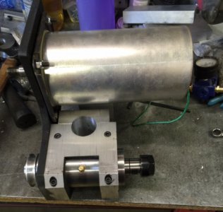
Building A Tool Post Grinder

OD grinding, wheel and work spin same direction:
http://www.kanabco.com/vms/other_grinding/other_grinding_06.html

Reason given:
"This so that the surface of the grinding wheel and the surface of the workpiece are moving in opposite directions at the point of contact. This also reduces the possibility of ride-up or jamming that can occur if they were rotating in opposite directions."

NEMES (a hobbyist group) published this in 1958:
http://neme-s.org/Model_Engineer_Files/2996-Grinding Rotation & Dressing.pdf

They agree, but give different reasons. Mostly for coolant and grinding sludge control. They also allow for the opposite, and have no serious objections other than making a mess by throwing coolant and grit upward.

https://en.wikipedia.org/wiki/Cylindrical_grinder

Pretty much agrees that the work should run against the wheel in the opposite direction, reason given is smoother work and less chance of jam-up.

I think if I kept looking, I could find more sources that give either answer, and give some of the same, and some different reasons.

Thank you Tony, You have confirmed my findings.

These articles say exactly the same thing as all the rest. The grinder and lathe run in opposite directions ( the instances showing them in the same direction has the grinding wheel to the rear of the work which is the same as opposite direction when the wheel is in front) They at least give a reason. So.... I will follow the directions when I experiment with my grinder after finishing it.
 
Mark-Is it a problem to run your TPG spindle in reverse instead of the lathe?
Robert
No except you would be throwing the sparks and swarf upward instead of downward. I am concluding that running the spindle in the slowest back gear speed will be less of a hazard wile running in reverse. Besides, the grinding load is light, unlike when turning, so I think the hazards are minimal. I am pleased to see that this topic has stirred some discussion. this is good and how we all learn more.
 
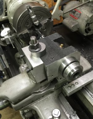
This is the completed post for holding the TPG. It is 1 1/2" diameter. The plate is 3 1/2" diameter and 1/2" thick. The plate was bored and pressed onto the post. It wont move. It may be overkill, but the TPG is really solid when mounted and besides it looks better to me , nice and sturdy :grin:. There should be no movement or vibration on this setup as it mounts solid and directly on the saddle. Now I can finish the height adjustment.
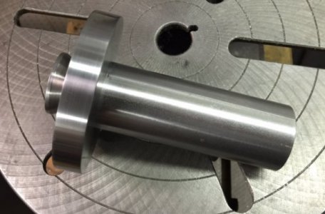
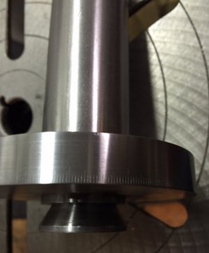
post 4.jpg post 5.jpg They are a little light, but I engraved degree markings on the bottom plate. I doubt they are really needed, but I put them there for reference. Once the grinder is mounted and set at spindle center height and locked there , it won't get moved. the grinder will be square with the "0" mark. There are 90 degrees on either side of zero. If I find I need them for some reason, I will stamp numbers on them. The marks are kind of light and small but as I said, they are just for reference.
 
OOPS !!!!!!

Just to let you know.....us old seasoned machinists royally screw up too.:bawling: It has been pointed out to me ( a big thank you to Nelson Collar) that by mounting my grinder on the cross slide, I lost the ability to grind tapers which is very important ( to me anyways). So....... I will be making a major revision requiring some remachining of the base and mounting it on the compound. It is not too bad....I just have to modify the mounting post and mill at least a half inch off the base block. I'm glad someone thought of this and pointed it out so I an fix it quickly. I find it hard to believe I made such a simple error :oops:, but I guess doo-doo happens. I'm still having fun though :grin:
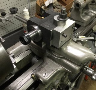
 
Ok ......... I went to the shop and checked my screw up. After some thought and an hour of hacking and cutting on the mill, the problem is solved.
image.jpeg
If you look close, you can see the 1 1/8" notch cut out in the bottom of the base to make room for the compound. Everything is as it should be now. Now I can get back to making the height adjuster.
image.jpeg
 
Nice save Mark. :)
I was originally going to mount it on the compound when I started, and then got the bright idea to put it on the slide instead of all the stacking , forgetting all about angles, so there was lots of material I didn't bother to cut off. I was also thinking of more room because the spindle is 2.200" diameter and must sit in front of the compound to drop to center height. This causes me to lose about an inch of grinding diameter. But I can try to make some of that up using a smaller wheel. I bought 3" wheels instead of4 or 5 inch wheels. But now they need to run faster to get the SFM needed. Everything has a snowball effect. The nice thing about the DC motor is the infinite variable speed. My motor is 4800 rpm. I will pulley it for 10,000 rpm at the spindle as that is the speed needed for most internal grinding. I just dial it back for external grinding instead of messing with changing pulleys. I ordered one of those little digital tachs to mount on the grinder and displaythe spindle speed . ( I haven't figured out the mounting for it yet though)
 
Last edited by a moderator:
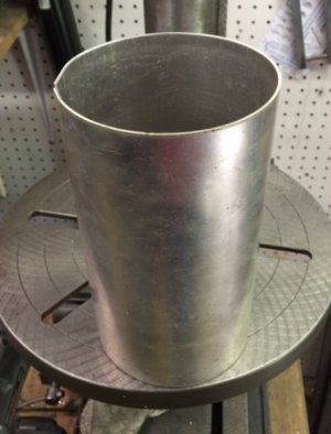
My good friend mike the " shade tree machinist" helped me make some covers in his shop.
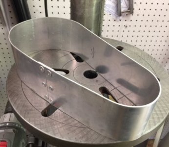
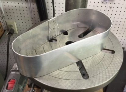
belt guard1.jpg belt guard2.jpg This is the start of the belt guard. I definitely want a belt guard on this thing at 10,000 RPM.
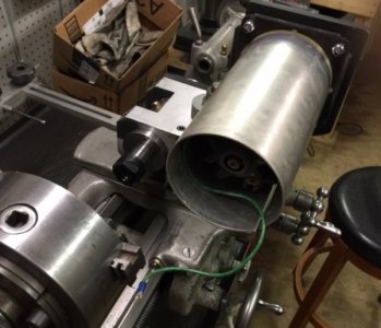
grinder13.jpg This is how the guard will mount. I still have to make the outside plate, but this was the hardest part.
motor cover.jpg We also rolled a cover for the treadmill motor.
grinder12.jpg It fits perfectly. I will make a plug or plate for the open end and put a vent in it.
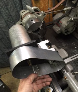
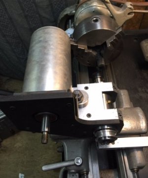
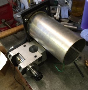
grinder14.jpg grinder11.jpg grinder 10.jpg These are a couple photos sitting on the bench and also mounted on the lathe. It is working out really well so far.
 
I do have one question though. I read in Dumore's instructions that the grinder turns CCW ( looking at the stone)or grinds downward. The spindle should rotate the other direction, but that is not a good idea with a screw on chuck. Does it really matter that much? I could reverse the grinder but it would throw the Sparks up instead of down. That was for external grinding , but for internal grinding , they say to run them the same direction. I don't understand why.

I don't think it really matters that much. But I have a screwed on chuck and have not had any issues with the chuck screwing off when using a grinder. You aren't removing much material when grinding and nothing for the material to catch on to cause the chuck to unscrew. (Assuming your chuck is like mine and requires a good deal effort to remove it after being used.) Reversing your grinder wheel might be the way to go and just let the sparks go up and fab a shield.

You could have made your grinder to mount on the backside of the lathe and turn grinder wheel CW; this would of kept the rotations correct and sparks downward.

On your other issue, the articles I've read say turn the spindle CW (reverse) when externally grinding and CCW (forward) when internally grinding. So their instructions are consistent, the grinding wheel/material always turning opposite directions.
 
My good friend mike the " shade tree machinist" helped me make some covers in his shop.
View attachment 129275 View attachment 129276 This is the start of the belt guard. I definitely want a belt guard on this thing at 10,000 RPM.
View attachment 129281 This is how the guard will mount. I still have to make the outside plate, but this was the hardest part.
View attachment 129277 We also rolled a cover for the treadmill motor.
View attachment 129280 It fits perfectly. I will make a plug or plate for the open end and put a vent in it.
View attachment 129282 View attachment 129279 View attachment 129278 These are a couple photos sitting on the bench and also mounted on the lathe. It is working out really well so far.
At 10k rpm, you need a guard on the wheel too.
 
Back
Top