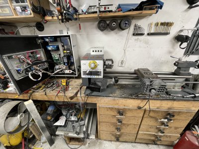
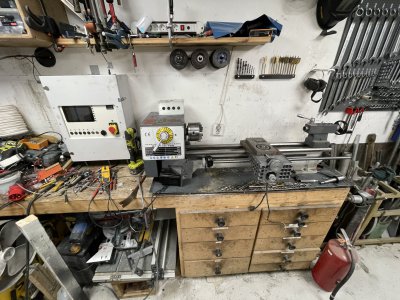
CNC conversion BL250G/700 lathe

Generally exhausted from life so progress is slow but I've started on the electronics.
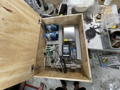
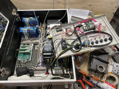
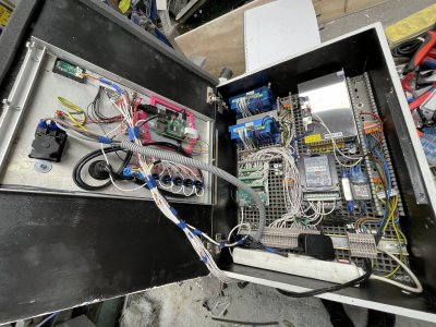
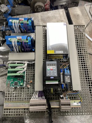
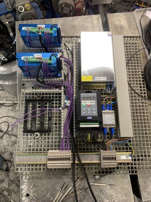
Will mount a alu plate along the middle to hopefully absorb some noise from VFD and PSU on the right side, also mounted a noise filter for the VFD.
All the "high" voltage stuff is on the right side and the "low" voltage is on the left side, I've tried but it's not a perfect split since the stepper drivers need 90VDC.
Stepper motor cables goes down to the terminals and will be wired directly to the "outside".
Encoder cables already had contacts on them so I just wired those into stepper drivers and are going to let them hang outside of the enclosure.
I wanted to do a proper job of numbering each cable but the printable heatshrink I bought refuses to work so I ran out of patience.
Black piece on the lower left is to hold the Mesa 7i96 but printer must've been out of calibration because it doesn't fit, will need to reprint before I can hook up step/dir/alarm/etc stuff to it and be somewhat done with the internals.
IMG_6830.JPG
 
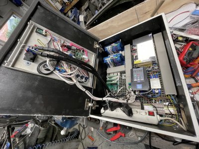
Slight redo, decided to splurge on a new labelmachine and shrinkwrap each cable with what they're for.
Normally you'd use numbers I guess but this saves me from keeping a seperate "cable list".
Longer cables out to the left will go to two status LED's, one for the enable signal and one for the alarm from the stepper drivers, a bit overkill since the UI will show this either way but figured it'd be nice to have.
Something I realized yesterday is that I need to be very careful with the voltages here ... The stepper drives expect 5V everywhere but the Mesa card outputs 36V on the I/O whilst it has 5V on the step/dir pins...
In other words, step/dir cables can be "direct" whilst anything connected to the MESA outputs need to be current limited before it hits the stepper drivers.
Furthermore need to figure out an adapter between the Mesa and VFD for spindle speed control and forward/reverse..
IMG_6871.JPG

Thinking out loud, trying to understand the control card.

Inputs/outputs general:

7I96 also has 11 isolated inputs plus 6 isolated outputs for general purpose I/O use. 11 isolated inputs provided for general control use including limit switch and control panel inputs. Inputs operate with 3V to 36V DC and can have a positive or negative common for sourcing or sinking input applications
The inputs are confusing me a bit, I see them just as "input low or high signal" and the card will only see that, but that logic only works for 0-5V (in my head anyway). Maybe this is settable somewhere. Furthermore there's 11 inputs and an "input common".
Later in the manual it says the 11 inputs are 4-24V and not 3-36V..?
Further down it says 4-36V, the manual seems to be very confused about what input signals it can handle.

All 11 Isolated inputs have a common pin. This common pin must be connected to ground for active high inputs (PNP type) and connected to the I/O power for active low inputs (NPN type)
So most likely for my use-case, the common will be connected to 5V and all signals will need to be grounding/pull-downs.

Six 36V 2A isolated outputs allow sinking, sourcing combinations of both.
This leaves me a bit unsure if the outputs can handle up to 36V or if there's a boost converter that outputs 36V.
Furthermore each output has both positive and negative terminal which could mean they're just VCC and GND but could also mean that they're for sinking or sourcing?

The 6 isolated outputs are completely floating switches so can be use for pull-up/pull-down and mixed voltage switching. The 6 isolated outputs use full floating MOSFET switches ( a DC Solid State Relay or SSR ) and can be used just like a switch or relay contact. Maximum voltage is 36 VDC and maximum load current is 2A. Inductive loads must have a flyback diode. The output polarity must be observed (reversed outputs will be stuck-on).
That clears up the outputs. Each is to be considered as a switch whilst polarity sensitive. Not shortcircuit protected so 2A fuse is probably good to have, even smaller is probably smart.

Inputs:
Input1: Emergency stop
Input2: Homing switches
Input3:
Input4:
Input5:
Input6:
Input7:

Spindle control/outputs:
AFAIK the 7i96 can't directly control the VFD but seems like it can output a PWM signal that can then be converted to 1-10V with a "PWM to DC" module.
Some kind of config tool should be able to change one of the stepper controller outputs into a I/O pins so I can run a PWM from there.

Output/spindle guesswork:
Output1: Spindle VFD CW
Output2: Spindle VFD CCW
Output3?: Spindle PMW -> PWMtoDC module -> VFD
PWMtoDC module seems to need 12-24V input.
This solution already occupies 3 out of 6 outputs. Maybe I can get more outputs/logic by disabling the extra stepper drivers.
Output4: Coolant/extractionfan on/off
Output5:
Output6:

Jumpers:
W2, W3, W4 control the encoder input mode. Right hand position for all is differential, lefthand is TTL. Not sure which to use yet.
W5, W6 select IP adress. Probably want down-down to use fixed 192.168.1.121
W7 jumper should be in up position to handle 5V I/O signals. This seems to only apply for the expansion connector.
W8 should need to be used since it's for a BoB.

Grounding:
Top left mounting hole next to ethernet jack should be grounded to frame for EMI resistance.

Expansion:
P1 is a 26 pin connector for more I/O's. Not sure if it can be used directly or if it needs a 'slavecard', seems to be 0-5V either way.
From what I can see it seems to be "ready to use".
All expansion I/O pins are provided with pull-up resistors to allow connection to open drain, open collector, or OPTO devices. These resistors have a value of 4.7K so have a maximum pull-up current of ~1.07 mA (5V pull-up) or ~.7 mA (3.3V pull-up).
Seems to reinforce my idea that the expansion can be used without any slave cards.
On startup the outputs can be high, potential safety issue depending on what it's controlling.
Whilst it can handle 5V it seems to output 0.4V to 2.4V.

Step/Dir parts:
Each integrated stepper controller seems to have 6 pins. 5V, GND, STEP+/- and DIR+/-.
The 5V pins are short circuit protected.

Various pins:
Pin 21/22(TB2 connector) are 5V in, mentioned as "logic supply power input" but doesn't go further into what logic, if it's obligatory or not etc.
5V logic power for the host interface FPGA, expansion connectors, RS-422 and encoder connections and step/dir connections can be provided at connector P3, or alternatively TB2.
So 21/22 feeds pretty much all connectors power. Since I already input 5V DC on the main power input(P3) I don't think this should be needed but seems weird they'd have duplicates like this, maybe I'm missing something.

Jog wheels:
Initially I thought I wanted a pendant but maybe 2 seperate MPG's might be nicer, with pendant it definitely happens that I move the wrong axis ..

Gearing:
There might be an issue with the spindles gearbox, if the control card is expecting a max speed of 1400 rpm when I have the gear for 500rpm or similar. I have seen some implementations where inputs are used to detect what gear the lathe is in but this would require A LOT of inputs on this lathe. Maybe there's a smarter way here using analog signals.

--------------------------------------------------------------------------------------
Will keep updating this as I figure things out to keep most of the mesa info in one post.
Edit1: Added spindle info.
 
Last edited:
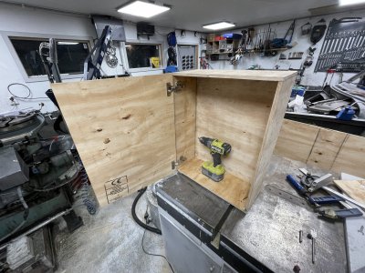
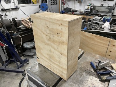
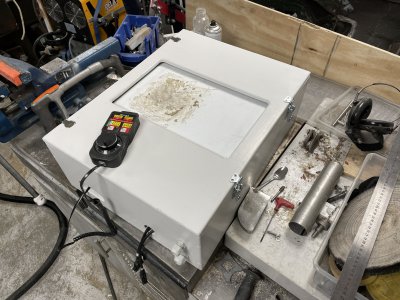
Been spending a ridicilous amount of time trying to find a suitable box to put this in, ended up just making one to keep moving forward.
About 25% the cost of something pre-made and I get everything exactly as I want it.
Self-closing and dampened hinges, will get some latches and a sealing strip around the door later on.IMG_7176.JPG

need to round off some edges and give it a quick paintjob before I start fitting in the control board.
IMG_7177.JPG
 
Spending an hour here and there on this project, really makes the documentation suffer but only way I can get something done at the moment.
Cut down my "grid plate" a bit and printed special mounts for it to sit securely in the box yet easily detachable.
Whilst it's not going to be taken out often at all, I don't want to have to cut cables and connections just to get it out for an overhaul.
IMG_7322.JPEG

Gave everything a few more cutouts, a quick sanding and some paint
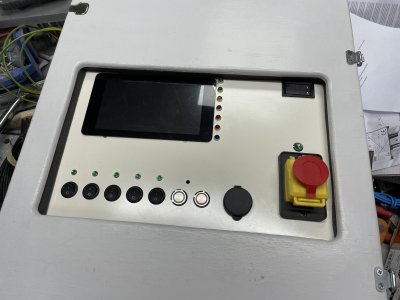
I'm so tired of running long cables for switches etc mounted in opening doors so this time I'm trying a fixed plate for all of that, which then seals against the back of the door.
The plate itself comes off with just 3 screws so it's easy to modify.
IMG_7522.JPG

So now I need to add the sealing strips everywhere and finish up the wiring.
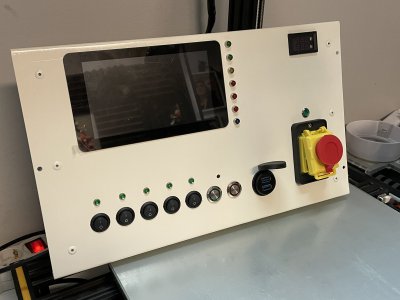
Part of that is of course deciding on a layout for my control panel/plate.
To be continued.
IMG_7521.JPG
 
Some machining followed by a quick sanding and paint of the surface.
Unfortunately I encountered some problems with fitting it in my mill.
I had already programmed my paths and was too lazy to split all the programming into two setups and all the work that comes with multiple setups...
My problem is as usual limited Y travel and a vertical head that's fairly close to the back of the mill so even though I have enough travel, the endmill doesn't reach far out enough before things hit the mill. That's a whole 'nother sideprojects I'm trying to not get into...
Either way, my "quickfix" of moving every 10mm up resulted in the top row being a bit too far up, a better solution would've been to just lower those and have a more compact layout but eh, hindsight and all that.
IMG_7629.JPG

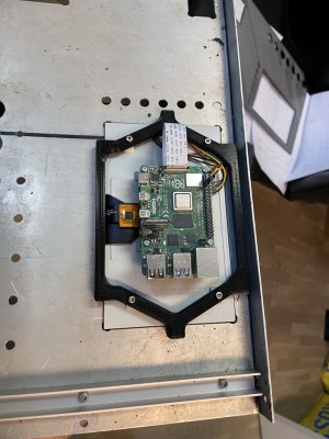
To fit the raspberry I printed a little bracket to keep it tensioned up against the frame.
IMG_7562.JPG
 
Well, that bracket was great, for detaching the screen. :eek:
Had to redesign where the bracket is screwed into the front panel and then screen is screwed from the back, with a slight airgap between the front panel and screen itself. I made sure to make the new mount as macho as possible. :cool:
IMG_7646.JPG

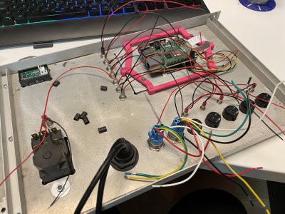
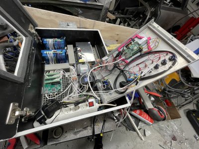
Spent quite a bit of hours wiring already, nearing 10 hours since "fixed" the raspberry screen. Getting a lot done but hard to show in pictures.
This is the current mess of things. Added two more powersupplies(5V raspberry and 12V generic use) and a powerstrip for better "modularity" if I need to replace something.
Tried to keep everything as constrained as possible as I make more progress, makes it easier to find not-awful routing paths for all the wiring that cannot be hidden in the cable canals(is that even a word?)
IMG_7700.JPG

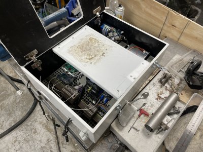
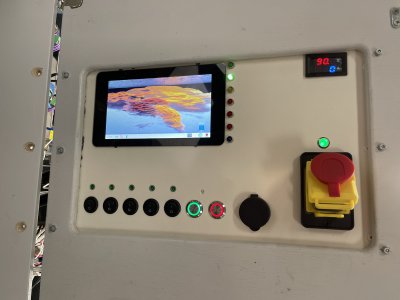
Ended this evening with adding some weather stripping. I want to prevent as much dust as possible from entering through the front, top and sides. I will also add a fan with a filter to make sure the case is over-pressurized which should help keep it's insides clean. Since I do a lot of dirty work things can quickly get a nasty coating of dust and grease/oil.
It's probably more visible here that I accidentally placed the screen and power monitor(top right) too far upp due to my milling travel issue earlier. It will still work and it doesn't bother me enough for a redo.
IMG_7702.JPG

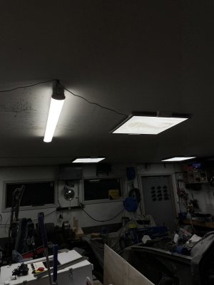
Of course there was also a side-project. Felt like I was breaking my eyes by managing all these small wires and tags.. Went and bought a cheap 44W LED light fixture, basically like the good ol' tube lights but crammed full of LED strips I imagine.
The 'square' next to it is, or was, a 40W light fixture.. It's hard to catch in a photo but the squares are light a dim bulb in comparison to the new fixture... Made a MASSIVE improvement to how easy it was to keep everything in check. It's also very noticeable when taking photos because they're much sharper when under that light compared to the other ones. Need to invest in getting some more when I'm not broke.
IMG_7699.JPG
 
Like, I should know this by now, but it absolutely baffles me how long wiring takes.'
From the last photo I'm sure no one can tell the difference without having them side by side, but this is 3 hours of semi-efficient work.
IMG_7714.JPG

-Wired up all the switches and their corresponding LED indicators, got lazy and skipped the resistors, we'll see how much that bites me later.
-Added a whole bunch more sockets/connectors on the DIN rail.
-Wired all the in and outputs I'm going to use, everything that can't be connected(because external equipment or such) is labeled and wired down to the DIN rails.
Inputs as following:
Alarm from stepper drivers(combined, don't care if it's X or Z, just stops the software)
HomeX
HomeZ
Gear 1 (The idea is to let software know what gear I'm in so it can figure out max RPM.)
Gear 2 (Lathe has 12 gears but I think 3 + VFD gives me more than enough range)
Gear 3
Start cycle
Stop cycle
Any unused is wired to DIN rail for easy connection later.
Outputs: Enable signal to stepper drivers, FWD and RWD to VFD and probably something more I've forgotten about.
-Installed the PWM to 0-10V converter that will let the Mesa card talk to my VFD

I am REALLY unsatisfied with my approach of having a fixed control panel. It made so much sense in my head but it's awful to work with. Would recommend to have it mounted into the door instead, makes wire routing much easier.
Furthermore the 15mm plywood I've used is much too floppy to work well. It works, just not well.
 
After thinking about this for a few days I just went out and started cutting cables. :rolleyes:
Sure, I could've finished it faster as it was but any future modifications would've been utter rubbish to deal with.
Comparing this with the previous picture, I have to say it feels like the right decision even if it was 4 extra hours.
Another obvious thing is that I should've made the entire cabinet ~10cm taller for more space along the bottom, always something that gets ya.
But eh, TLDR of what I've done this round:
-Cut down the control panel a bit on the width, drilled new holes and bolted it to the cabinet door, added bonus is that this reinforced the door quite a bit so it stopped bowing everywhere.
-Redid the 3-phase "entry" completely and moved it to the left side so it doesn't need to stretch over the entire cabinet.
-Removed/disloged every single cable from the control panel and extended them enough so I can place them neatly later on.
-Temporarily used blue masking tape to hold the loom together, once I'm happy with placement etc I can make a permanent less-temporary solution.
IMG_7740.JPG

What needs to be done:
-Install a fan to make sure cabinet is well ventilated.
-Route, cut to length and rebrand and connect every single cable I've extended.
-Investigate a few wires that have no marking and I'm not sure where they came from.
-Doublecheck the jumpers on the Mesa board to make sure they're set correctly.
-Double check the jumpers on the PWM to 0-10V board.(Mesa can only do PWM, VFD can only do 0-10V...)
-Figure out which wire is + and which is GND for the mesa power supply.
-Power up the raspberry and install LinuxCNC
-Power up the Mesa in connection to the raspberry and run the mesa configuration tool(and pray I haven't wired something wrong. :confused 3:)
-Tidy everything up and close the cable gutters.

Once that's done, the control cabinet should be "done" and ready for installation next to the lathe so I can start hooking the lathe up to it.
-VFD to the motor
-Homeswitches to the mesa card
-Spindle encoder to the mesa card
-Stepper motors and their encoders to the stepper drivers
-Connect some kind of keyboard/mouse/trackpad combo to the raspberry.
etc etc etc etc.
 
Alright, episode 3749 of the neverending story.
Spent quite a bit of time finishing up the cables, possibly not enough time.
Was finally time to connect power to this thing, and it worked great for around 5 seconds. :rolleyes:
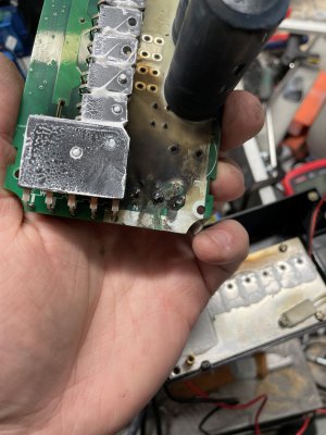
Unfortunately I had assumed some details and hadn't even properly looked into it, sending my VFD to greener pastures.
Not to mention that it tripped both the high-tolerance RCB, the 16A fuse for that outlet AND the houses 20A mainfuses. :confused 3:
I usually find that just having the outlets fused to be enough for machines but in this case it's clearly obligatory to have a fuse in the control panel as well, it is extremely annoying have to replace the main-fuses and restart everything else in the house..
IMG_7847.JPG

Eventually identified the problem, VFD only supports 220V main voltage(line to line) in 3-phase mode, we have 400V in that mode so go figure.
Reconnected in 1-phase mode which should work well with our power grid.
Changed the plastic hose/cover that was previously gray. This one is much more flexible so it just works better.
"Fine-tuned" quite a lot of cables to make sure the stem holds together nicely and then started zip-tying things.
I was quite worried that the short circuit had damaged other components as well but even the raspberry pi seems to work fine.
IMG_7859.JPGIMG_7843.JPG

FINALLY mounted the stub legs for the control panel and secured it onto a wall right next to the lathe.
To make sure there's minimal confusion I removed the buttons on the lathe itself as they will have no function.
Also had to unbolt and lift the entire lathe out to rewire the motor, the VFD outputs 3x220V whereas the motor expects 3x400V. The workaround was to rewire it as a delta instead of star. It's a slight pain to not be able to access the rear of machines but that's the downside of lack of space I guess.
I really hope that all that remains now is to:
-Connect stepper motors, their encoders, the spindle encoder, VFD to motor, keyboard/mouse etc.
-Install/connect limit-switches
-Change raspberry pi operating system to linuxcnc
-Configure the Mesa cnc card
This is of course just for initial testing, if everything works out I still need to remake all the 3D-printed parts in aluminium or steel.
IMG_7865.JPGIMG_7864.JPG
 
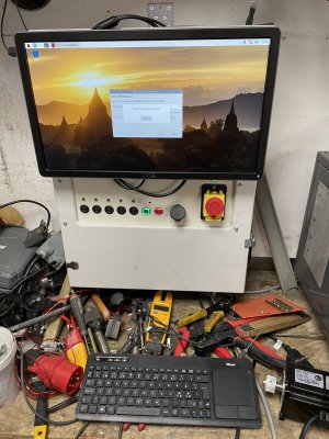
Slight change of plans. Quickly noticed the 7" screen was never going to work, it's just too small.
Optimal would probably be 15" or so but it's a hard size to find. Found this 20" for nearly no money at all instead.
Obviously can't see all my indicator lights I so carefully positioned so need to revise that sometime, not urgent.
IMG_7896.JPG

Connected 98% of the wires now and the rest has been software work. I think I would honestly rather rescrape the entire machine again than redo the LinuxCNC installation. :confused 3:
Very steep learning curve when you're used to Windows and GUI's for everything.
Got things mostly working now, VFD still won't select forward/reverse properly but it's highly motivating to finally see some movements!
 
Last edited:
Back
Top