More small steps of progress.
Spun up some nylon bushings for the telescopic cover to ride on, I don't like the idea of it sitting directly against the ballscrew.
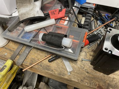
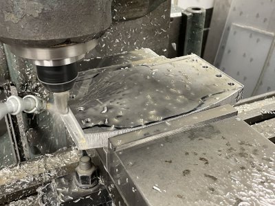
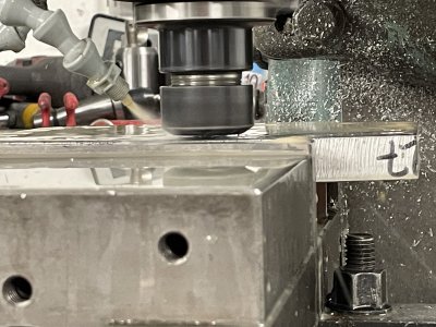
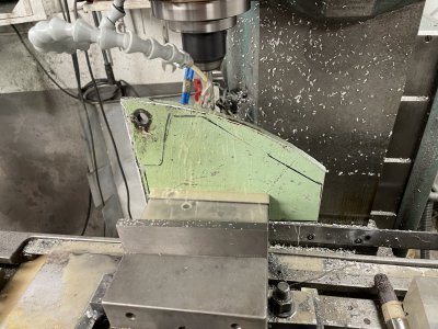
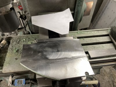
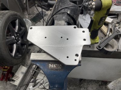
Then realized the mount still wasn't finished and resumed work on that... Needed a thicker piece for the next step, so first I need to clean up this scrap. Quite messy ordeal cleaning off scrap but also quite fun, since you're milling more volume you can experiment a lot more with pushing the various endmills/tools. Cleaned most of it off so I can more easily use the rest of it in the future, of course little to no regard for surface finish here, just flattening/cleaning it up.
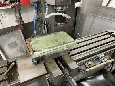
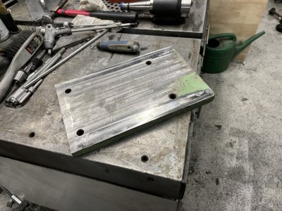
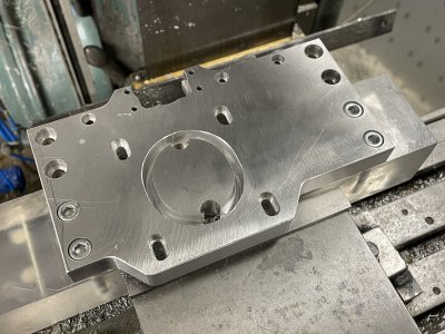
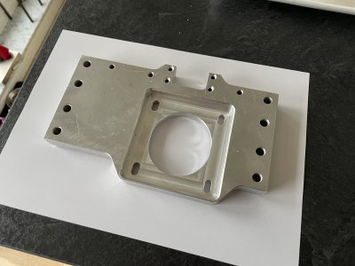
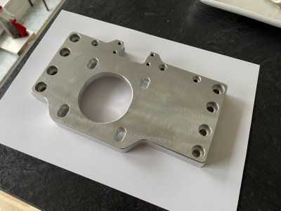
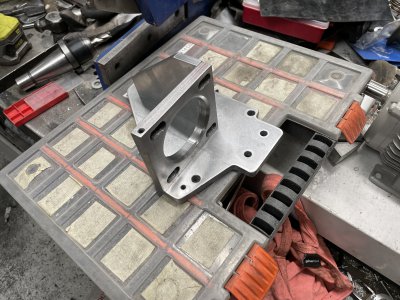
So all of that work for this little piece.

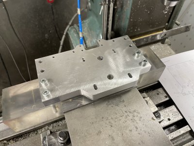
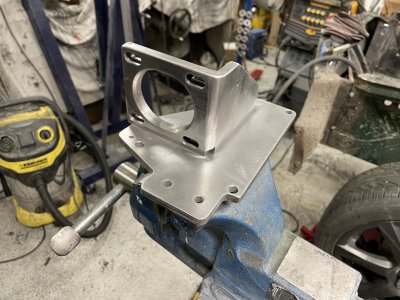
The baseplate and "addon-piece" are reamed to 8mm and then I used two dowels to align everything, clamped down and welded it together.
It was at this point I realized my mistake, the 8mm holes were supposed to be offset to one side on the addon block, so the block now sits too far to the left.
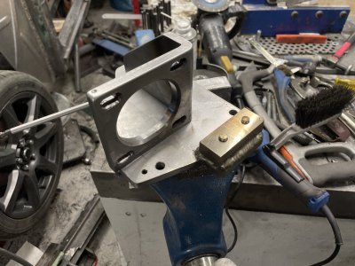
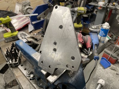
Nothing that can't be fixed with the metal glue gun(MIG). The piece got ridiculously hot as I laid down bead upon bead to add material to the right side.
I was intentionally somewhat aggressive to see if all that heat would warp things, and by how much. After blending everything down I can't really tell what's warped and what's just my own grinding, so seems this kind of thickness is very forgiving when already welded all around the perimeter.
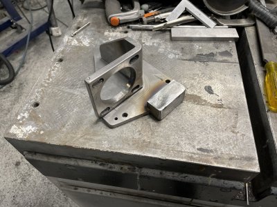
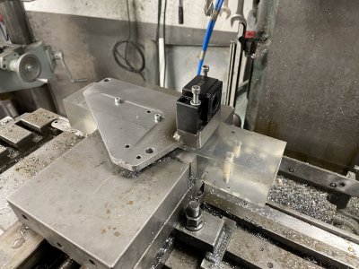
Next step was trying to reorient it in the mill so I could drill the 4 holes in the raised block.
Since I know the coordinates of the other holes, I took 2 at random and drilled/threaded into a block and zeroed to those positions.
This then let's me use the DRO to see where the remaining 4 holes need to be. Half-threaded two of them to sanity check some things, especially that the 'lip' on the right was at the correct distance to help support the bearing block.
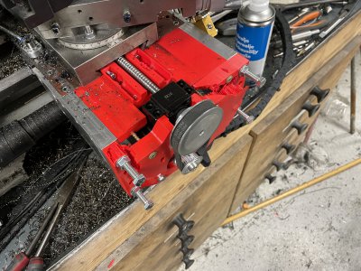
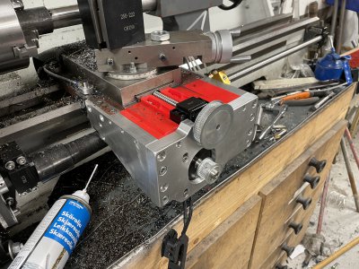
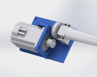
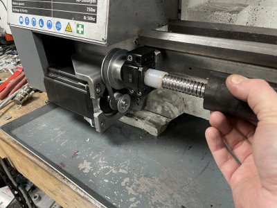
And finally installed on the lathe. One big oversight was that I had to cut a slot in the "loop" around the axle. It's so tight here that the motor can just about be slid in from the front, it's impossible to 'angle it in' like otherwise would have been needed.
I put some hotglue around two of the nuts behind the motor so one does not need to hold them from rotating which is otherwise a pain on the "hidden" screws.
One might notice the bearing block is only held by 3 screws.

Even tho I was being very careful, one of the stainless screws galled up and got insanely stuck, ended up having to snap it off. It now acts as a positioning pin and I'm sure the other 3 screws will be plenty.
So that's a somewhat finished Z-axis. Pretty fun mixing machining with welding and blending and has definitely made me less scared of introducing deformation.
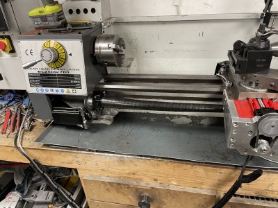
As with everything else, always tons left to do.
"Must-do":
-Replace red plastic with metal.
-Fabricate cover that should sit ontop of red plastic part.
-Replace current cable chain with a larger one that can hide behind/underneath lathe instead of in front.
-Add some kind of security to spindle stalls(I think LinuxCNC can solve this internally by comparing RPM to set value).
-Change VFD setting from forced braking to free-spin on turnoff, if spindle is stalled this should let it instantly be off instead of winding down over several seconds, still applying torque.
-Finish the side panels on the X-axis by 1. drilling/threading for the side mounted fasteners and 2. Milling out more clearance on the left panel around the telescopic cover, this can at the moment get pinched if moved all the way to the left and is hard to spot = risk of breakage.
-Change how the spindle encoder is mounted. It is currently bouncing around as it's (badly) directly mounted to a shaft. I want to decouple it with a belt instead to reduce risk of wobbling and all the issues that bring with it(bad readings, short life etc).
-Double-check the spindle gearbox for leaks as the left of the lathe often seems oily. Maybe somehow add a better oil sight-glass to check level.
-Reorient/cover the oil hoses as they're currently dragging around and are at risk of getting caught in stringy chips.
-Figure out how to oil/grease the ballscrews correctly. X-axis is currently just a M6 thread sticking out, need to figure out some fastener I can push oil/grease into. Z-axis has a grease fitting under the X-carriage. Might just go with grease on both.
-Add a flatspot to the X-axis ballscrew. Both X and Z has at some point spun, visible superficial damage on both shafts. I assume this was from any of the crashes but I need to make sure the pulleys can't spin on the axles.
"Nice-to-do":
-Add some kind of cover to the left of the carriage to protect the ways/make it easier to clean.
-Replace compound with solid mount.
-Add fixed positions to the QCTP to reduce risk of it rotating and make tool table data reliable.
-Write a component and add switches to gear selector so LinuxCNC "understands" what RPM is available(ie can't reach 1600rpm when in 80rpm gear and vice versa).
-Add homing switch to X(will probably not give a perfect reading but better than having no idea each bootup).
-Add some kind of tool-probe function to quickly measure in tools.
-Limitswitches on both ends of both X and Z. X runs risk of both dropping the ballnut and crashing, Z runs risk of crashing both directions. Not something I'd rely on but could still save your behind in some situations.
-Redesign the rubber cover extending towards the back of the X-axis. It's an older design that no longer fits correctly/tightly.
-Replace the plate that holds the Z-nut. It's hidden under the X-axis and is 3d-printed plastic. It might introduce flex but it's also a bit of a safety from crashing Z as I imagine it will break first. Low priority.
-Add a control panel on top of lathe for easier handling. This is quite a bit of work.
Most likely need a daughter card to interface with the current controller card, for more inputs/outputs and is mostly a quality of life thing.
Could implement nice features like:
-Powermeter to see how much more I can push it.
-Rev/Off/Fwd buttons for when you're doing half-manual work like drilling with tailstock.
-Spindle/feed overrides for quickly adjusting mid-program. Preferably rotary with click function that could quickly reset to 100%.
-Start/pause/stop/emg stop buttons that are easy to reach.
-Any indicator lights that could be good to have clearly visible.
-Joystick/Jog buttons combined with Touchoff X/Z buttons for ease of use.
etc.
I already have most things(except the daughtercard) at home but I think I will prioritize other projects/tasks for a bit as this in itself could easily be 2 months of work.
