CNC conversion BL250G/700 lathe

Things are really on the move now! :grin:
Finally got everything calibrated and working.
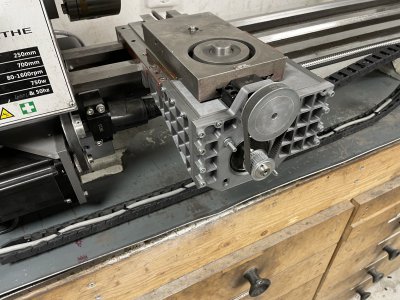
After testing things on the bench I assembled everything.
Finally added the extendable screw cover, need to make up two brackets so it doesn't just lay on the screw.
I should also change the location of the cable chain, I might be able to make it go underneath the bed, around the backside.
IMG_7934.JPG

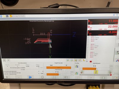
I have to say the GUI is pretty nice, makes it very clear what dimensions you're going for.
Much better than what I'm used to from Mach3.
IMG_7939.JPG

Handcoded that program quickly just to test things out. Most hardware is still printed plastic so I'm not expecting greatness.
To my surprise it works really good! Of course this is just plastic I'm working on but still.
Ran the lathe at 1600 RPM(default max rpm) and I think 500 mm/min so ~0.31mm per rev.
MUCH faster feed than I ever ran manually when trying to stop at a set point.
Now I just need to replace the printed pieces with steel or alu and I'll be set!
 
Last edited:
Nice CNC conversion, it's cool to see some LinucCNC stuff on this forum.

I'm in the process of CNC-converting my milling machine using a Mesa 7i96S.
 
It's a very capable combo, just too bad that it's not very user-friendly. The learning curve is much steeper than for example Mach3.

I've started pushing things a bit harder to find failure points and weaknesses. Definitely got more than I bargained for. :grin:
Unfortunately when I was pushing too hard, the spindle stalled. As the spindle stalls, my keyboard also stopped working so I couldn't stop the program. Whilst I have an emergency stop on the cabinet, it will kill all power and risk damage to components, so this is for BIG emergencies..

This resulted in a show of bruteforce from the steppers, applying more and more torque until the side panels sheared right off.
Lessons learnt:
-Don't use wireless keyboards.
-Have a proper stop button.
IMG_8050.JPG
 
I would recommend using only PS2 keyboards, not just avoiding wireless keyboards.

The PS2 ports are supposed to be on an interrupt, but are probably buried in the chipset these days. It's still my preference, but these are getting harder to find.

I believe that somehow technology is going backwards.
 
Sounds like a good solution, will look into that/your thread!

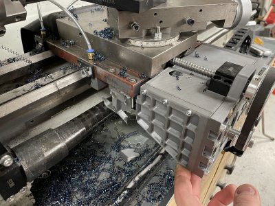
Started remaking the busted sidepanels in aluminium, I'm confident enough in the design that I don't need more plastic prototyping.
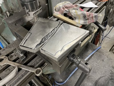
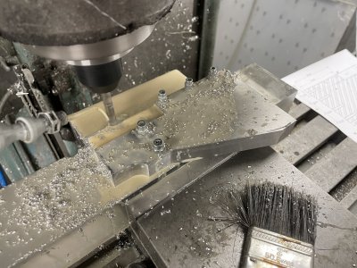
Had some 20mm scraps I cut the rough outlines out from, made a quick and dirty jig and followed up with some contourmilling and a lot of drilling.
Had quite a lot of fun cutting these out on the coldsaw.

IMG_8053.JPGIMG_8060.JPG
Took an extra 3 hours because I completely messed up the 4 holes on the fronts/thin edge.
Drilled with 4.2mm for M5 threads and did such a poor job at centering them that I had to go up to M8 to be able to fix it.
Initially plunge-milled with a 6mm endmill to straighten things out and then went in with a 6.8mm drill for M8, overkill but saved the parts.
There's no visual damage on the printed part holding the Z-screw nut so I'm keeping that for now.
So far gotten real lucky with the fit of these parts, probably saved a lot of headache testing my measurements with the printed parts first.
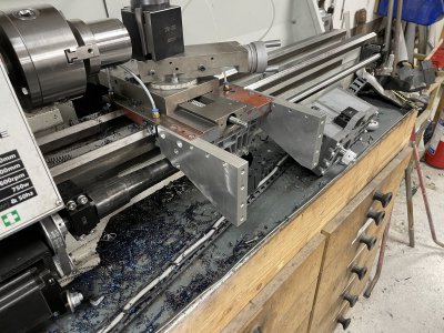
These parts are roughly twice as thick as the printed pieces. Not only did this allow me to properly countersink/bore the screwheads but it also let me envelop the original casting a bit nicer.
IMG_8069.JPG
 
Last edited:
can you program an overcurrent shutdown into your CNC controller? It seems that strengthening one part will simply shift the failure point to something else in a crash. Also curious why you still have the compound - wouldn't a solid riser be sufficient (and stiffer) for a CNC lathe?
 
I need to look into the VFD manual. It has a relay output you can somehow program, possibly I could use that to trip the CNC alarm when it's stalled/overcurrent.
Possibly LinuxCNC could be used to check the spindle encoder and cancel if RPM is too low. No idea how to accomplish that though.

Main reason for replacing/strengthening the mounts is to reduce flex, if it crashes with full aluminium mounts, something expensive is definitely going to break. A working 'casual-emergency-stop' and a few safety features need to be implemented to make sure nothing major happens in the future.
I want to also implement a power meter for the spindle, it is incredibly difficult to get a feel for how heavily loaded it is, being able to clearly see the amount of load would quickly let you know if you're pushing too hard.

I'm only keeping the compound at the moment since I haven't had the time, energy, motivation, money etc to sort out a solid riser. It's on the list of todos. :grin:
The gib on the compound is fully tightened down so it's not useable and quite a bit more rigid than it normally is.

Goal at the moment is to just get this functioning(reliably) so I can finish some minor stuff on my 1938 Storebro lathe and then resume working on my project car.

Todo-ish as follows:
Fabrication:

-Make front plate in aluminium.
-Make top plate and screw cover in aluminium.
-Make banjobolts to redirect the oil hoses.
-Make Z-axis motor plate in steel/alu.
-Make X-axis belt cover(optional, I highly doubt it needs one)
-Replace compound with solid riser(Low priority)
-Make centering rings for the Z-axis telescopic cover, currently it's dragging on the screw which is not good for longevity.
-Make new mount for spindle encoder, with belt-drive to cause less stress on the encoder shaft.

Control:
-Doublecheck emg-stop button, add a second one on top of lathe.
-Look into if VFD can output overcurrent alarm to emg stop program
-Add power meter for spindle, clearly visible somewhere.
-Replace the pos keyboard(ordered another type which has been very reliable on my mill cnc conversion)
-Double check that spindle encoder is working correctly so I can rigid tap and single point thread etc

Various:
-Doublecheck spindle gearbox for oil leaks(guess who drilled/tapped through the casting without considering what was behind it)
-Mount counterweight to the rear of the saddle/carriage to compensate for all the crap mounted up front
-Replace current X-axis cable chain with a larger one that goes behind the lathe(less vulnerable to chips).
-Replace 750W motor with 1100W motor(Low priority)
 
Last edited:
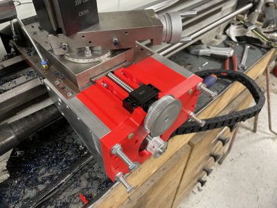
Temporary printed pieces in red, also adds 15 horsepower to the spindle because race color.
Did quite a few design changes on these pieces which is why I opted to print them first to check fits&function.
IMG_8071.JPG

Some more cutting later. So hard to find good feeds/speeds compared to the mill. Good finish won't break chips.
Good chip breaking won't give good finish etc.
New weird issue with the LinuxCNC installation, every now and then it won't let me type into the console/command window.
Or it lets me type but then jogging doesn't work. Could be malfunctioning keyboard, not sure, but highly annoying.
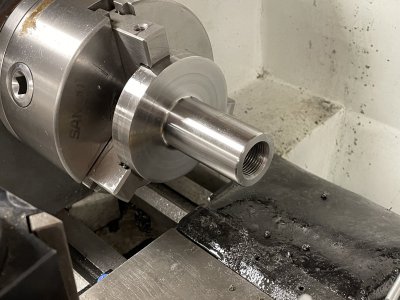
Slug used to be ~80mm diameter. Reduced ~60mm of it to 31mm, drilled it out and tapped it M20.
Programmed in a radius where the cut transfers from Z-axis move to X-axis move, turned out pretty nice and should reduce stress.
I did chicken out and tap it manually though.
Not sure what steel it is but it's incredibly tough so I'm real happy with the lathes performance.
IMG_8077.JPG
 
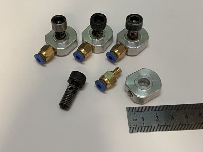
-Make banjobolts to redirect the oil hoses.
Not the prettiest item but was an interesting use of the CNC. Really need to work on my fixturing to get more repeatable runs when swapping multiple parts etc.
Hopefully the aluminium shoulder will be enough to seal against the bolthead and casting.
IMG_8080.JPG
 
Back
Top