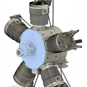
Edwards Radial 5 build thread --- PHOTOS!

If this works out I may have to try one to. I already have an airplane to put it on.
I've got the opposite situation --- no plane to put it in. I've actually never flown an RC plane before, and frankly have never had much an interest in it. Just buildin' it for the buildin's sake.

Looking good, following along. I'm building an Ohrndorf 5-cyl radial. Quite similar to the Edwards dimensions & overall layout (and my first go at anything this complex). If you want to read about my grizzly details I can link my post over on Home Model Engine Machinist. There have been a few Edwards builds documented there btw if weren't already aware.
Cool! Shoot me over the link to yours! I've seen a few of the threads over there on the Edwards, and am definitely using some of the tips/tricks/tweaks those folks incorporate.
 
Get a dremmel or high seed pneumatic from HF and the diamond bits or dental burs and carefully cut it out.

Whenever you visit the dentist ask what happens to the old burs as often they are thrown away.

Sent from my SAMSUNG-SM-G930A using Tapatalk
 
Definitely watching this one. Since you are so close to me (2hrs away) AND I fly RC, this could work. LOL.
In fact, I am hoping to start building a bird this coming winter that would be a good fit... ;)
I have seriously looked at Moki radials, but never considered building a radial. I am really curious how you are going to go about making the cylinders.
Thank you for sharing the build. Oh, by the way, I always (or so it seems) break the tap on the last hole.
 
Since you are so close to me (2hrs away) AND I fly RC, this could work. LOL.
In fact, I am hoping to start building a bird this coming winter that would be a good fit... ;)
I'd consider that. But if you crash it, you'll owe me a new one!

I am really curious how you are going to go about making the cylinders.
I've already had a few failed cylinder attempts! But I've now got a good path forward. Look for that in Episode 8(ish).

I think Episode 9 or so will bring me up to current day. So everything prior to that is something that I've been working on over the past few weeks, but just haven't yet had a chance to write up. Hope to post a couple today to try to catch up a bit.
 
I'd consider that. But if you crash it, you'll owe me a new one!

Crash?! I try not too. LOL. Actually, the airplane I am hoping to build would not do aerobatics or anything, just a large scale flyer.

I really was just joshing you about putting that in my plane. I don't know if I could get over the hump of "what if something went wrong" and I wrecked your engine. Of course, if you insisted.... LOL
 
Episode 4 || (Mis-) Adventures in Dissolving a Broken Tap

As I stated in a prior post, I broke off a #4-40 tap in the (beautiful) crankcase I had just completed. I tried the usual 'grab it with a vise grip and twist' technique with no luck. And a #4-40 is so small, there's no real way to get a traditional tap extractor on it (and would almost certainly not of worked anyway, because they never work). I don't have a welder, so no ability to weld a nut to it. I have a few carbide drill bits and end mills on hand, but none small enough to drill out such a small tap.

As was suggested by @Lo-Fi a few posts back, I had recently come across a video or two on YouTube showing how one could dissolve a broken HSS tap out of a chunk of aluminum using the proper mixture of chemistry and witchcraft. I thought to myself, this would be a perfect opportunity to try it out for myself. After all, a #4-40 tap is small so it shouldn’t take all that long to dissolve.

So I got to re-watching those YouTube videos. They all make it look incredibly easy. The sorcery basically goes like this: let the broken tap in your part sit submerged in a saturated, near-boiling solution of alum and water. After a few hours, the tap will be completely dissolved, and the part will be completely spared, save for maybe a little bit of cleanup. Sounded good to me!

So I got started.

Step 1.
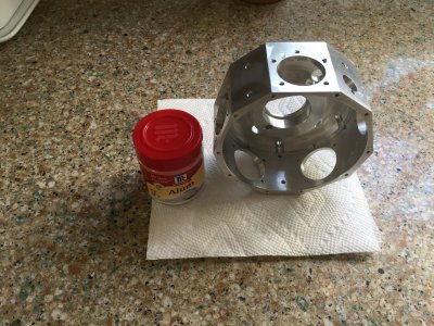
I had never even heard of alum before watching those videos. So I was surprised that you can find it in a regular spice container at any grocery store. I guess it's used for canning or pickling or something. My local grocer only had 4 little containers of it, so I bought it all. Didn’t know if that was too much or too little, but it was pretty cheap. Maybe $4 per canister or something.
IMG_7038.JPG

Step 2a.
This was an embarrassing failure on my part. And I originally took a couple photos, but deleted them because it was so dumb. I’m going to share anyway. Oh well.

I grabbed one of my wife’s small Pyrex food storage containers and filled it about 2 fingers full with water, just deep enough so I could put my part in and submerge the tap. I then dumped one of the containers of alum in and stirred it around a bit. I then put it on the gas stove directly over the open flame. Well, that was stupid. The Pyrex neatly broke into a few pieces after a couple minutes, dumping hot alum-water all over the stove. See, I had always thought Pyrex was made from borosilicate glass, which is what is used in chemistry labs world-over and exposed directly to Bunsen burners and the like. I was wrong, it’s not. (To be fair to me, Pyrex used to be made from borosilicate glass until something like the mid-90s, and still is made from borosilicate glass across the pond. So our Euro brethren shouldn’t have much the same experience.)

Step 2b.
I wised up right-quick and switched over to a crockpot. I similarly put in just enough water, and dumped in an alum canister. All that dissolved at room temperature, so I dumped in another. I dropped in the part and cranked up the crock. About halfway through, I dumped in my final alum canister. While I’m not sure I ended up with a completely saturated solution, it seemed pretty darn concentrated to me.
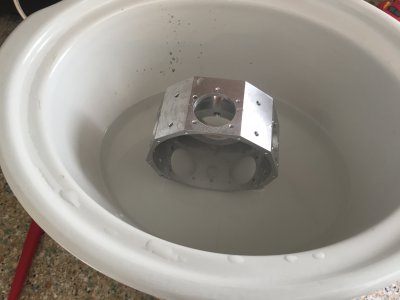
IMG_7039.JPG

Step 3.
I waited. And waited.

~75F: nothing.
~100F: nothing.
~125F: nothing.
~150F: nothing.
~175F: nothing.

Finally, at somewhere around 200F (not exactly sure, but it was hot), a steady stream of bubbles started coming off the tap. WAHOO! It was working!

So then I waited some more, the plan was to wait until all the bubbles were gone, which would obviously signify that the tap was gone.

After something like 5 hours, the bubbles coming from the tap had largely abated. There were still some bubbles forming, but they were coming from other parts of the crankcase and didn’t have the same vigor as before.

Step 4.
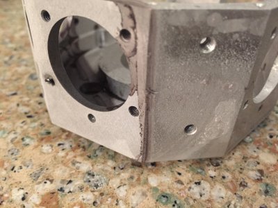
Having waited long enough, or as long as I was willing to wait anyway, I pulled the part out and rinsed it off. As I had been checking things the whole way along, I was both dismayed and unsurprising to find (1) the tap was completely intact, and (2) my part was a now a complete mess, not only below the waterline, but everywhere.
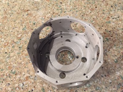
IMG_7046.JPG IMG_7047.JPG

It was a little bit hard to tell whether the grossness on the surface of my crankcase was due to pitting or buildup. Buildup is in theory clean-able; pitting, not so much. I suspect it was a buildup of alum, but couldn’t be sure. Seemed to be some pitting as well, though I'm not sure the chemistry going on supports that hypothesis.

I briefly tried cleaning up the surfaces, but geez, it was a huge pain in the ass. And because of the weird geometry, I’m sure there would have been large areas that never got cleaned up, and big scratches and gouges in other parts of it.

It was ugly now and would always be ugly. So I decided to scrap the part and start again.

This would afford me the opportunity to fix some of my prior mistakes, so I wasn’t all that bummed. In fact, it was a pretty fun part to make, so spirits are still high.

My next post will be a relatively short one about re-making the crankcase.

TIME ON TAP REMOVAL: 2 hours
CUMULATIVE TIME: 50 hours
 
Last edited:
So I decided to scrap the part and start again.

Oh no! That's both the worst and best feeling I've found when working on a project, the moment you realize you just need to start again. All the mistakes you made, and all the little things that you wish you'd done better come up and you get to think about doing it better this time!

That said, I suggest a tapping head. I realize they are expensive, but after working with small taps on my engine project, I cannot help but think that there is no better way to stop from breaking taps. As careful as I have been, I REALLY want to just get one so that I can stop breaking taps!
 
Sorry to hear that! Maybe the tap was so small there wasn't really enough surface area for a reaction?

Either way, might I suggest making a simple tapping fixture? Seems it'll be useful on this build!

 
Episode 5 || Crankcase, Round 2

I’ll make this one quick because it’s much the same as the first go’round.

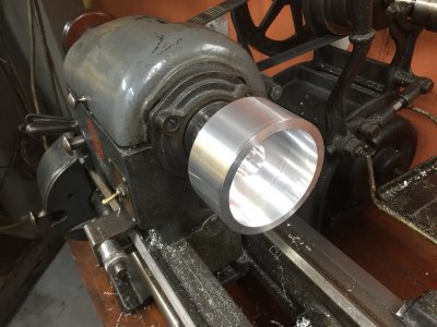
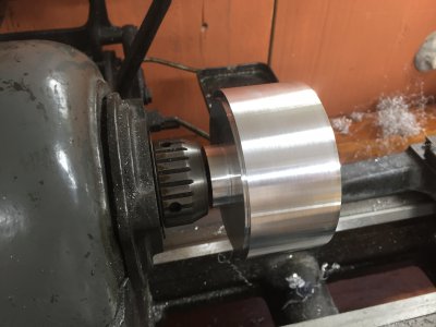
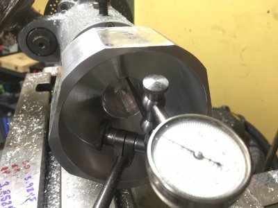
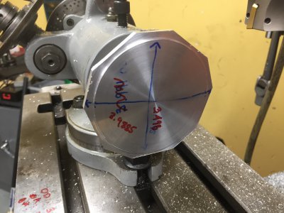
I had to buy new stock, so I started out with a 4”-diameter chunk of aluminum rather than the 5” I used for round 1. That made roughing a lot easier and faster. I also opted to hold the part differently: after roughing most of the stock off while chucked up in a 4-jaw, I turned a 1/2” spigot on one end for holding in a collet. I would have much rather used a larger spigot, but the largest collet my lathe can accommodate is 1/2”. The purpose of this was to use the same 1/2” spigot to hold in a collet at the dividing head, which would hopefully increase concentricity and reduce overhang.
IMG_7080.JPG IMG_7081.JPG

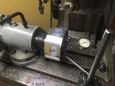
Dividing head operations the second time were much the same as the first time. Problem this time, though, is the small 1/2” spigot was simply too small and led to a bunch of flexibility. I again had to indicate everything in all over the place. Again, a big pain. Not pictured are all the clamps I used to hold everything firmly after I got it indicated. This all could have been solved with a H/V rotary table / dividing head stood upright. I still don't have one of them though. :)
IMG_7082.JPG IMG_7083.JPG

The new setup resulted in most things turning out better than the first crankcase, but not everything. On this crankcase, the flats all ended up with a small amount of taper (up to maybe 5 or 10 thou end to end, don't quite remember), which was inconsistent from flat to flat. I’m hoping that the taper is too small to matter. But if it isn’t, I’m confident I can make up for it with some differential pressure while sanding the bases of the cylinder barrels when I make them. No biggy.

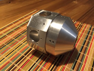
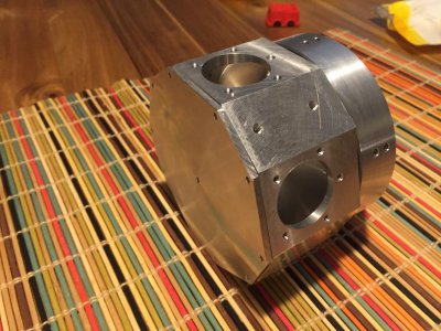
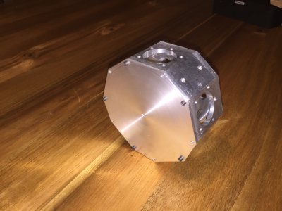
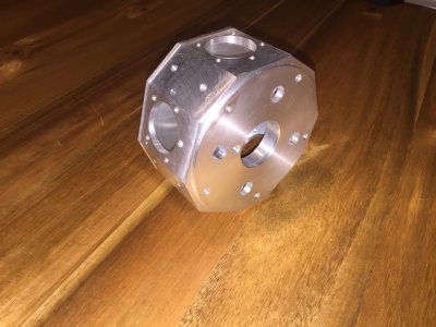
Anyway, I didn’t take all that many photos because I wanted to get it done with and it was essentially the same as the first attempt. Here are a couple teaser photos a few steps ahead after I finished the Cam Housing and the Back Plate. It’s definitely coming along.
IMG_7086.JPG IMG_7087.JPG

Overall, I’m reasonably pleased. It’s not perfect, but it should be plenty close enough to be functional. And if it isn’t, I’ll just make a third!


TIME ON CRANKCASE #2: 18 hours
CUMULATIVE TIME: 68 hours
 
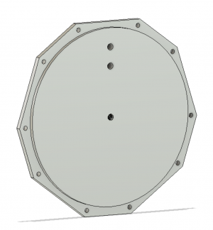
Episode 6 || Rear Cover

This will be another short one. Pretty simple part, particularly because I was already adept at dividing out 10 divisions on my dividing head. Which is actually quite easy, as it’s just 4 complete spins of the handle (40:1 worm), ending up in the same hole every time. Made things way easier than they’d have been if I were building a 7- or 9- cylinder engine.
Fusion_01.PNG Fusion_02.PNG

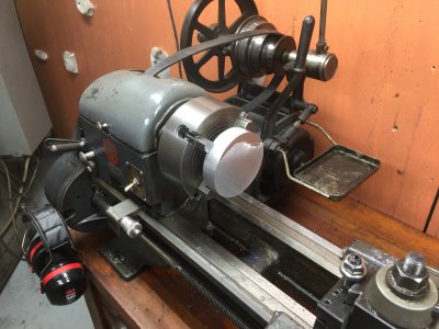
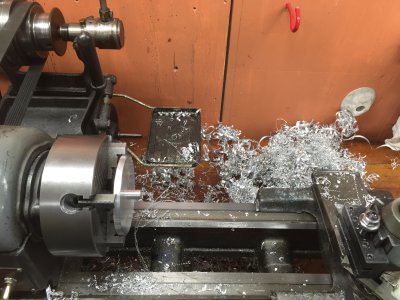
The technique I used to hold the rear cover was similar to my second go-round with the crankcase. I first chucked the whole thing up in a 4-jaw and rough machined everything, including a 1/2” spigot (again, would have liked it to be larger, but that’s the collet capacity of my lathe) so that I could hold it in a collet in both my lathe and the dividing head. A bit of wasted stock, but that’s life.
IMG_7059.JPG IMG_7061.JPG

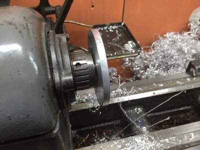
Once the spigot was turned and thing were rough machined, I flipped it around in the lathe, holding it in a collet by the spigot. Did my finish turning, and brought it over to the dividing head on the mill, where I milled the flats to match the crankcase.
IMG_7062.JPG IMG_7064.JPG

All that was left was to machine off the spigot and punch out a few clearance holes for the #2-56 socket head cap screws used to mount it to the crankcase. Things line up pretty damn close when the cap screws are installed. There are still two more holes to punch in the back plate, but it’s basically done.
IMG_7176.JPG IMG_7175.JPG


Quite happy with this part, no issues at all.


TIME ON REAR COVER: 5.5 hours
CUMULATIVE TIME: 74 hours
 
Back
Top