Has anyone installed Clough42's electronic leadscrew on a PM machine?

That is a timing belt and cogged sheaves driving the encoder, right?

Great point - the stepper is locked "in step" with the spindle via the encoder. The encoder ought to be connected to the spindle via a cog belt such as HTD-3M or similar so that the spindle and encoder always stay in sync.

In addition I think you will find that the "gear" on the spindle itself that meshes with the change gears is a T5 pitch so you can add a T5 pitch pulley to the encoder and drive it direct with a belt.
 
When I say not steady, it rotates, slows then rotates slows, and appears to be affected by the load on the feed screw or lead screw. I liken it the servo having to catch up. The lead screw and the feed rod behave the same. I have removed the servo and worm gearbox and rotated the input to the lathe gearbox and it rotates smoothly, but there is defiantly some resistance to rotation. Thread pitches are all correct and feeds are good also. Over about 125 RPM I do not notice it. At this time I have not rerun the servo software to tune the servo. The servo is at 1000 steps per rev. The encoder is driven off the 40 tooth spindle gear to a 60 tooth gear mated to a 60 tooth GT2 pulley driving a 40 tooth pulley on the encoder. I have no issues taking .050 DOC cuts at 300 or so RPM using a HSS tool. I have not done the math on the feed rod or lead screw but i believe its fairly slow like 1 RPM at 75 RPM spindle speed.
 
As a side note to what I mentioned above, the worm box drag plus the lathe gearbox drag may be almost too much load on the servo. I can make a cut with it but it doesn't take a lot to stall the feed rod. Might be too low of RPM for the servo to make full torque? I have been thinking of trying a 7.5:1 box to see if that helps. I got the worm box from Stepper Online from their eBay store for about $50.
 
Maybe the torque is really low at very low stepper speeds? You could get 10:1 by switching your gearbox to 2:1 and then when you're feeding at .002 it would actually be feeding at .001. I found with my ELS that there is a fair amount of drag in the feeding gearbox of my similar lathe vs the cheaper direct drive to the lead screw lathes. I was able to gear mine down with pulleys and it worked without issues but it was clear that if i was feeding with the lead screw vs feeding with the power feed shaft there was less load on the stepper motor. One might assume you're threading at 75 RPM so you might already be using the lead screw while having this issue?

Are you using a NEMA 23 motor? Are you powering it with 24, 36 or 48 volts?
 
Last edited:
I will try the 10 to one idea and report back. Yes its the same Nema 23 servo motor Clough used. Running at 48 volts. I initialy was running 36 and did up it to 48 to see if it changed anything. you can see it in both screws, but i have no idea if it does so at normal threading ratios.
 
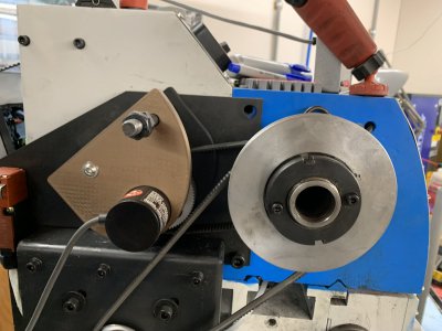
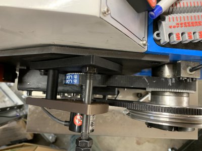
After a LONG time (and a couple errors) I Finally had time to tear apart the lathe (1030V) and install the bench tested ELS (Clough 42)
It is working (not tested thread pitch yet of course) and all seems to work well.

The only issue I have is keeping the darn connector in the servo. The power has screws, but the others do not. It is a bit cramped in there to plug them in anyway (under the ways), although I did not have any issues getting the servo in there on the mount I 3D printed.
I suppose a dab of silicone? I am open to ideas.

I hooked up the programming cable too, as long as it is not hooked up, leaving it connected seems ok- then I can change something if needed. Am I wrong?

Thanks for all (especially Tammy) for the help getting it all together. I will have the final 3Dprint files if anyone wants them (or I could print them). But best to wait until I run it awhile and make sure no mistakes. I already goofed up on the encoder mount. It was fine on the slow belt speed, but would hit on high. I have never used the high speed (and maybe never will) but silly not to fix it so I can. It was an easy change in Fusion 360 and just send to printer.

Mark
 
Last edited:
I tidied the wiring, made sure good cover around servo. It works great! I did some thread testing and came out just right.
I notice the servo seems to make some noise when just sitting- so I will try adjusting the ‘stiffness’ a little. It is not bad, but may as well see if I can make it better.

First project for it is a pair of hub pullers for my 66 Lotus Elan with ‘knock off’ wheels. One left hand, one right hand- 10 tpi. The ones for sale have both in one tool, but I think will be easier just to make two of them.
 
Out of curiosity, those using the same servo as James, what ‘stiffness’ setting did you end up with? With the ‘11’ default installed, it would make noise. I lowered to 8 or 9 and it is silent.

Edit: belt is loose in photo, that is why it appears not aligned. I made a mistake on the outer encoder mount, so I had to reprint and didn’t have any of the CF PET. That is why the different colour. There is a bearing on the inner mount and all the force is on that bearing- just the flexible drive to the encoder transferring the motion.
 

Attachments

  • IMG_7840.jpeg
    IMG_7840.jpeg
    309.2 KB · Views: 66
  • IMG_7842.jpeg
    IMG_7842.jpeg
    323.4 KB · Views: 65
Last edited:
For others who may be trying to source timing pulleys for their ELS project I need to share my “boy do I feel dumb” moment. Finding HTD 3m or whatever flavor belt/pulley combo you need in the correct bore/tooth count was quite challenging. Finally dawned on me I have a lathe! I bored out some pulleys I had on hand to 16mm for my drive shafts. Then had a pulley that I trashed by making the bore a hair oversize. Needed a 6mm bore for an encoder so grabbed some rod and turned a bushing with 6mm bore to press fit into the 16+mm pulley. Carefully drilled out the bushing and ran a tap through the set screw holes to clean them up. They work great with less runout and wobble than the original parts.
What did you do about the keyway for the output shaft (to the leadscrew)? I can actually buy a set of both pulleys for next day delivery on Amazon for an HTD 5M set. The 20T has the correct 8 mm bore for my servo. But the 60T pulley is only 10 mm (not the 14 mm I need). I can bore it to size, but there's no keyway...just a setscrew. I could run the setscrew into the slot where the key goes.

For the encoder, I can go direct from the spindle "gears" (assuming they match the T5 profile). SDP has a 40T Acetal gear with a 10 mm bore. I can 3d print a bushing to bring that down to 6 mm and it should last forever since the encoder won't have but a minuscule load. I can include a clearance hole in the bushing to allow the set screw go thru.
 
Last edited:
Buy the 10 mm one, bore it out like you said and cut a new keyway. I'm in the process of doing that myself. I just made a tool yesterday to cut the keyway. Here is a couple links of how others have done it. Mine is simple, more like Blondihacks.


Back
Top