Being a "craftsman" at your chosen pastime is better than anything and you can be proud of that.Mark, I consider you and Bill G both to be shining examples of true 'hobby machinists', and cornerstones of what this site is supposed to be. I will never be as good as either of you, but continue to learn from you both, as well as others here. My hat's off to both of you gentlemen.
And Mark, your description of how you rounded the area around the hinge pin support is exactly how I would do it. My machines are here to support me, not the other way around. I spend more time hand making/fitting parts than using my machines. My pistolsmith mentor had to use machine setups to fit 1911 barrels because he had so many to do. I spent over an hour last Sat. hand fitting one with files and stones and it came out perfect. Guess I'll never be much of a machinist. Maybe more of a craftsman.
-
Welcome back Guest! Did you know you can mentor other members here at H-M? If not, please check out our Relaunch of Hobby Machinist Mentoring Program!
You are using an out of date browser. It may not display this or other websites correctly.
You should upgrade or use an alternative browser.
You should upgrade or use an alternative browser.
My Next Project - A Metal Brake
- Thread starter Mark_f
- Start date
The bending brake is starting to be a lot of fun to build now that it is starting to look like something.
I drilled and tapped the holes to mount the thickness adjuster brackets on the base ends. I also machined the micro adjusters that mount on the clamp ends. The following photos show the parts and how they fit on the base ends. The bolt will be replaced with a knob for adjusting.
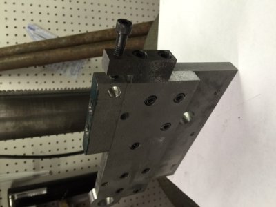
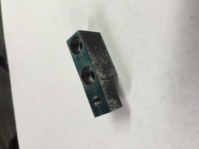
I want to take a moment here to explain how I locate holes in parts. I am not blessed with a big mill and DRO systems to accurately locate holes, so I do it “ old school”. A good example is drilling and tapping the holes for the micro adjusters. I laid out the first hole with layout dye and a scribe. It is drilled and tapped and the part bolted in place as shown in the photo.
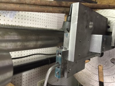
Since this is a ¼” hole, I use a ¼” bit to go in the hole and “sot drill the start of the hole for tapping. Next, loosen the part and move it out of the way. Use a tap drill and drill the hole. It will be perfectly located. I do this anytime I need perfectly matched hole locations.
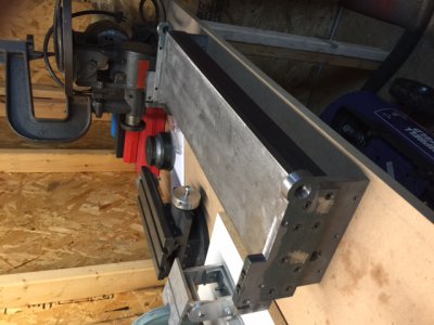
Now , on to more building. This completes the base unit for the bending brake. The next photo shows the completed assembly.
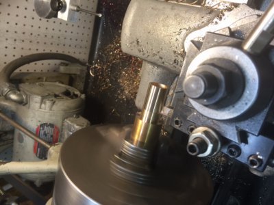
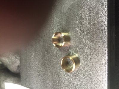
The hinges are to have bronze bushings in them. I found a scrap piece of bearing bronze big enough to make them. I put it in the lathe and turned the OD .0005 larger than the bore for a “light” press fit into the hinge. The ID is a slip fit for a .625” dowel pin. After turning , I simply parted off two .510” long bushings as shown in the next two photos.
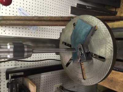
To begin the clamping assembly. I cut two pieces of .500 thick steel plate to size and also sawed a 45 degree angle on the ends. The edges were then squared and cut to size on the mill. The next step I s some holes. There is a .625” hole and a .500” hole that has to be identical in both plates so I clamped the plates on my drill press. Again, not being blessed with a large vertical mill ( I could go and use a friend’s mill, but I want to show another way for those who don’t have access to big fancy equipment.)
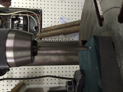
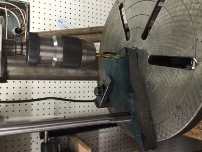
I laid out the two holes on one plate, center punched the locations, and clamped the two together on my drill press table. I put a pointed stylus in the drill press and lined up the center punch mark, keeping the edges of the plates aligned also, and then tighten the clamp. I drill a .250” pilot hole . The next drills and reamer are longer, So I put the end of the .250 drill bit in the hole I just drilled and lower the table and the drill with it. Then tighten the table clamp. This keeps my part aligned with the chuck and lets me get the clearance needed for the next longer drills. The hole is then drilled larger in steps and finally reamed to size with a .625” reamer. Next I move to the location of the .500” hole ad repeat the process. I stuck the .625 reamer in the hole to keep the plates aligned while drilling the second hole, as shown in the next photo.
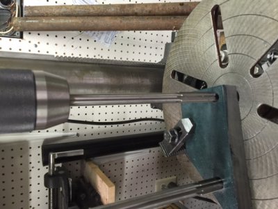
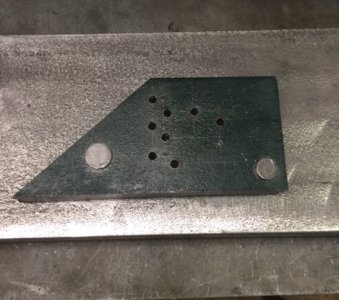
The next photo is the plates two plates stacked with matching holes. I slipped a piece of drill rod in each of the holes to keep the parts aligned while drilling several bolt holes which have been laid out on the top plate and center punched.
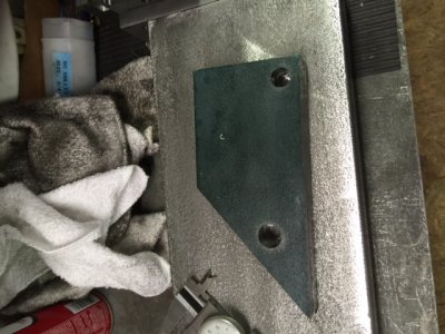
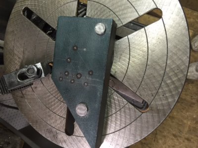
After drilling the eight holes with a tap drill , I end up with identical plates. A right and a left. These holes are frilled to be tapped ¼-20, but that will be done later, as these holes first will be transferred to the corresponding parts.
After machining the step pins the plates are installed to check the fit.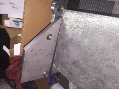
I drilled and tapped the holes to mount the thickness adjuster brackets on the base ends. I also machined the micro adjusters that mount on the clamp ends. The following photos show the parts and how they fit on the base ends. The bolt will be replaced with a knob for adjusting.


I want to take a moment here to explain how I locate holes in parts. I am not blessed with a big mill and DRO systems to accurately locate holes, so I do it “ old school”. A good example is drilling and tapping the holes for the micro adjusters. I laid out the first hole with layout dye and a scribe. It is drilled and tapped and the part bolted in place as shown in the photo.

Since this is a ¼” hole, I use a ¼” bit to go in the hole and “sot drill the start of the hole for tapping. Next, loosen the part and move it out of the way. Use a tap drill and drill the hole. It will be perfectly located. I do this anytime I need perfectly matched hole locations.
Now , on to more building. This completes the base unit for the bending brake. The next photo shows the completed assembly.

The hinges are to have bronze bushings in them. I found a scrap piece of bearing bronze big enough to make them. I put it in the lathe and turned the OD .0005 larger than the bore for a “light” press fit into the hinge. The ID is a slip fit for a .625” dowel pin. After turning , I simply parted off two .510” long bushings as shown in the next two photos.


To begin the clamping assembly. I cut two pieces of .500 thick steel plate to size and also sawed a 45 degree angle on the ends. The edges were then squared and cut to size on the mill. The next step I s some holes. There is a .625” hole and a .500” hole that has to be identical in both plates so I clamped the plates on my drill press. Again, not being blessed with a large vertical mill ( I could go and use a friend’s mill, but I want to show another way for those who don’t have access to big fancy equipment.)

I laid out the two holes on one plate, center punched the locations, and clamped the two together on my drill press table. I put a pointed stylus in the drill press and lined up the center punch mark, keeping the edges of the plates aligned also, and then tighten the clamp. I drill a .250” pilot hole . The next drills and reamer are longer, So I put the end of the .250 drill bit in the hole I just drilled and lower the table and the drill with it. Then tighten the table clamp. This keeps my part aligned with the chuck and lets me get the clearance needed for the next longer drills. The hole is then drilled larger in steps and finally reamed to size with a .625” reamer. Next I move to the location of the .500” hole ad repeat the process. I stuck the .625 reamer in the hole to keep the plates aligned while drilling the second hole, as shown in the next photo.


The next photo is the plates two plates stacked with matching holes. I slipped a piece of drill rod in each of the holes to keep the parts aligned while drilling several bolt holes which have been laid out on the top plate and center punched.


After drilling the eight holes with a tap drill , I end up with identical plates. A right and a left. These holes are frilled to be tapped ¼-20, but that will be done later, as these holes first will be transferred to the corresponding parts.
After machining the step pins the plates are installed to check the fit.


When I am finished the complete write up with photos will be available in a PDF file. I can't include the prints on here as it may be a copyright issue. However, if anyone wants they can email me privately and I can share my revised prints with all my changes with the PDF fileComing along nicely. Thanks for taking the time to outline all the steps. Mike
I worked on making the eccentric cams and handles. I hate doing eccentrics because I always screw up the offset amount, but these came out ok after a lot of work.
I turned the handles from 1/2 cold roll bar stock and the eccentrics from some mystery metal that is supposed to be CRS bar stock.
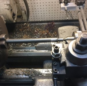
This photo is turning the handles.
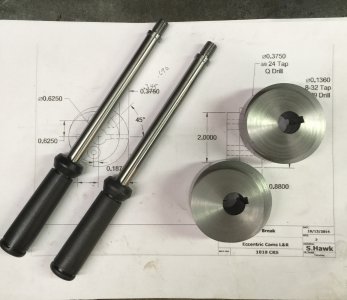
I turned the eccentrics and broached the keyway. A friend has some broaches so I did that at his shop. ( I got to get a set of those. That is definitely the way to make keyways. It only took a few minutes.) Those neat tapered vinyl handle grips came from McMaster Carr. They really add a nice touch.
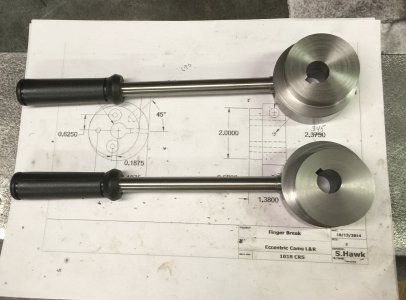
The eccentrics and handles are complete. Notice there is a right one and a left one.
I turned the handles from 1/2 cold roll bar stock and the eccentrics from some mystery metal that is supposed to be CRS bar stock.

This photo is turning the handles.

I turned the eccentrics and broached the keyway. A friend has some broaches so I did that at his shop. ( I got to get a set of those. That is definitely the way to make keyways. It only took a few minutes.) Those neat tapered vinyl handle grips came from McMaster Carr. They really add a nice touch.

The eccentrics and handles are complete. Notice there is a right one and a left one.
I made the reach shaft. It is a piece of 5/8" drill rod , 28.200 inches long. it gets a 3/16" key way in each end but they must be clocked to the same position on each end.How to do this took some thought. I put the drill rod in my vice on my little horizontal mill and cut the first key way. Now I need to flip it around and do the same on the other end but need a way to keep them aligned. So I drilled a hole in a small aluminum block, put it on the end with the key way cut and set it at 90 degrees with my digital angle indicator. Now , I can turn it around and align the block to 90 degrees and my next key way will match the other end perfectly.
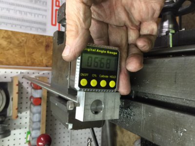
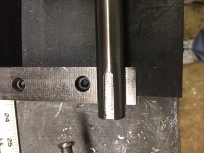 This is the finished key way. There is another just like it on the other end.
I found a scrap piece of bronze just long enough to make the reach shaft bearings.
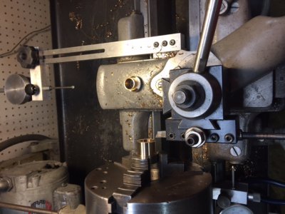 One bearing complete and turning the second one. There was only about a quarter inch of material left after making the bushings.
Since the base unit is complete, I will disassemble it and paint it this weekend. I have chosen a bright blue paint in the wrinkle finish. I like this stuff because it is baked on and holds up really well.

 This is the finished key way. There is another just like it on the other end.
I found a scrap piece of bronze just long enough to make the reach shaft bearings.
 One bearing complete and turning the second one. There was only about a quarter inch of material left after making the bushings.
Since the base unit is complete, I will disassemble it and paint it this weekend. I have chosen a bright blue paint in the wrinkle finish. I like this stuff because it is baked on and holds up really well.
Last edited by a moderator:
It took me a while to think up a way to keep the key ways aligned, and then this idea just hit me.Love the use of the digital indicator. Learn something new every day. Thanks Mark!
I made the eccentric straps today. Most people would have made these on the rotary table, but I find it much, much faster to do them by hand. It takes me hours to set up the rotary table and dial it in, make a fixture to hold the parts and then there is cutting them. this adds up to hours.
I laid out the part on the pieces of steel and center punched the center hole location. from this location, I used my compass scribe and laid out the lines of the part. I cut the corners off in the band saw, then clamp the piece on the mill table to mill close to the line. i keep turning the part and mill close to the line until i get all the way around. I end up with a roughed out piece as shown in the next photo.
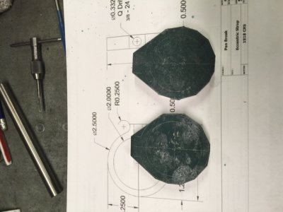 If you look close you can see the lines. I now take these to my belt sander and grind to the lines while turning the piece. This whole process has taken about 30 minutes. If you are careful you can make them so it is hard to tell they were not milled.
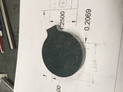 This photo is the piece after sanding. next will be to chuck the part in the lathe and if all was done correctly, the center punch mark will be in the center when the chuck is spinning. (When I chucked it up and started the lathe, the punch mark was within .010"of center.)
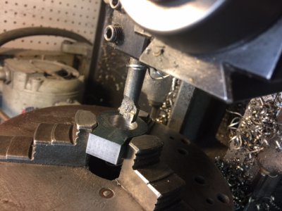 This is one of the smaller pieces being turned. there are four total. Two large ones and two small ones.
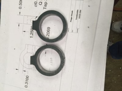 This is the larger two finished. The next photo is all four pieces finished. From start to finish these four parts took me about two hours. it would have been three times that dragging out the rotary table and setting it up.
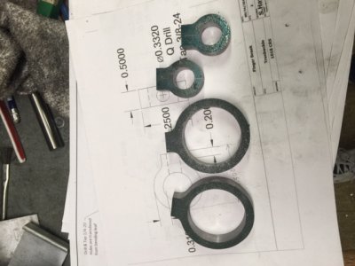 And here are the completed parts for the clamping system.
I laid out the part on the pieces of steel and center punched the center hole location. from this location, I used my compass scribe and laid out the lines of the part. I cut the corners off in the band saw, then clamp the piece on the mill table to mill close to the line. i keep turning the part and mill close to the line until i get all the way around. I end up with a roughed out piece as shown in the next photo.
 If you look close you can see the lines. I now take these to my belt sander and grind to the lines while turning the piece. This whole process has taken about 30 minutes. If you are careful you can make them so it is hard to tell they were not milled.
 This photo is the piece after sanding. next will be to chuck the part in the lathe and if all was done correctly, the center punch mark will be in the center when the chuck is spinning. (When I chucked it up and started the lathe, the punch mark was within .010"of center.)
 This is one of the smaller pieces being turned. there are four total. Two large ones and two small ones.
 This is the larger two finished. The next photo is all four pieces finished. From start to finish these four parts took me about two hours. it would have been three times that dragging out the rotary table and setting it up.
 And here are the completed parts for the clamping system.