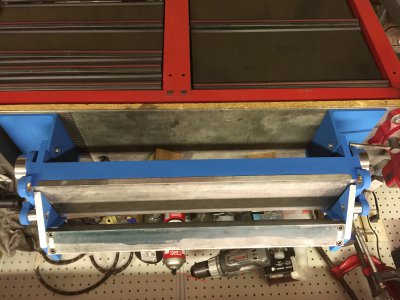
My Next Project - A Metal Brake

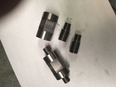
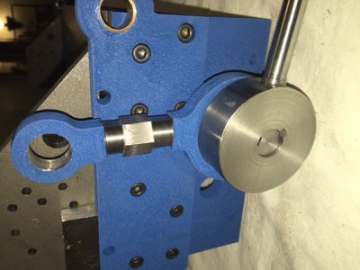
It took me all day to make two little turnbuckles. I started making the. threaded studs first, two left hand and two right hand threaded pieces. I didn't have any 3/4" hex stock to make the nuts and I wasn't about to buy a few feet to get three inches of the stuff. so......I turned some round stock down to .875" diameter. this is the distance across the wide point of 3/4" hex. I drilled and tapped the holes, a right and a left in each one. I had a left hand tap and die so I used those thinking it would be easier than single pointing the threads, but now I not so sure it was any faster or easier. they are done anyway. I used my hex collet block to cut a hex in the center of the round turnbuckle nuts so they can be adjusted with a wrench.
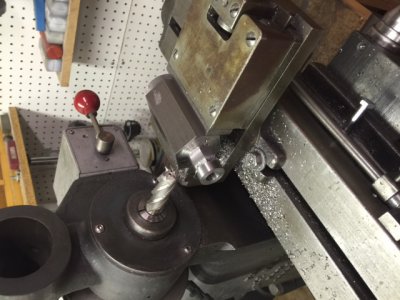
IMG_0521.JPG Cutting the hex on my mill.

IMG_0522.JPG The finished turnbuckles. Each one has three pieces.

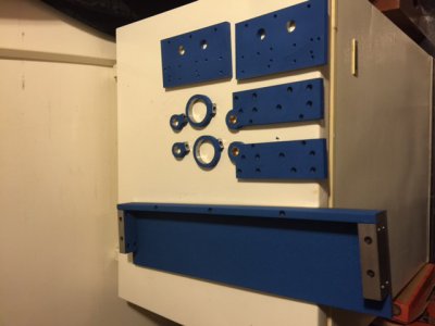
My former SWMBO has gone away for two weeks, so I am painting the finished parts and baking them in the kitchen oven. I am using a bright blue wrinkle finish. I hope I like it cause I got three cans for this project.
 
The paint is cured and time to assemble the base of this brake.
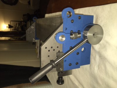
IMG_0526.JPG Here the parts are assembled to check the fit.
IMG_0527.JPG Everything seems to fit well with no problems so far.
IMG_0530.JPG Here I made the pins for the clamp.
IMG_0529.JPG If you notice, I have turned down the ends of the turnbuckles. They look much better this way.

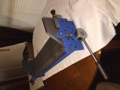
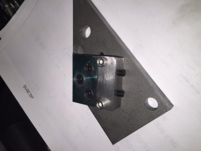
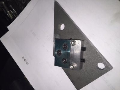
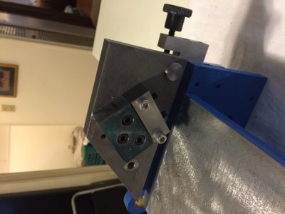
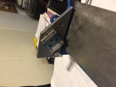
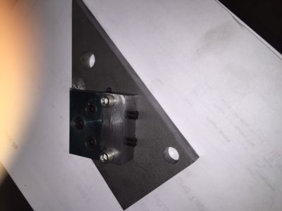
IMG_0532.JPG I removed the clamp end plates to make the finger bar brackets. The prints call for a 5/8" X 1 1/2" block for the bracket. I have increased the size to .750" thick X 2" wide. I believe this will help make the assembly more stable under pressure. The bolt holes are on size and have zero clearance. This also will help make the unit more stable.
IMG_0533.JPG I also increased the size of the support block under the bracket. Again I used zero clearance holes, and the set screws are under pressure to keep the blocks tight and stable. With these assemblies beef up, I am also increasing the size of the finger bar from 5/8" X 1 1/2" to 1" X 2" This is more than twice the mass of the finger bar in the prints. I think this will make a more stable clamp and hopefully I won't need the truss assembly. We shall see.
IMG_0536.JPG
IMG_0535.JPG These photos are the ends reassembled to the base. They will get painted soon. I need to make the finger bar first. IMG_0531.JPG IMG_0534.JPG
 
Looks great as usual Mark.

I love the paint you are you using, any chance you could post some specifics on it?

One word of caution, I would try to keep paint of the bolting surfaces, at lest at final assembly. You don't want the paint to undermine your bolt preload or shear resistance.
 
I was planning on building this brake at one point and I modeled it in CAD, as I was going to CNC some of the parts, and I would need the models done anyway. One issue that I found is that it's ability to make boxes and pans is fairly limmited because brace that holds the fingers is fairly close to the frame. I'll be interested in how it works out once you have it completed, as it looks quite heavy duty. I'm interested in what capacity it will bend, as well. Take care.
 
Looks great as usual Mark.

I love the paint you are you using, any chance you could post some specifics on it?

One word of caution, I would try to keep paint of the bolting surfaces, at lest at final assembly. You don't want the paint to undermine your bolt preload or shear resistance.
I have used wrinkle paint for years. It used to be easily available but is harder to find now. The brand is "VHT" (very high temperature). It is available in black at AutoZone stores, but the other few colors available, I order from amazon. It is kind of costly, around $11 per large rattle can. In order to get the best results and a good "wrinkle" finish, it needs to be applied in at least three good coats letting "tack up" between coats. Then bake in an oven ( I use my kitchen oven) for about 20 minutes at 225 to 250 degrees. the paint will harden as it cools. I like it because it is a durable finish and adds a "rich" look to a project.

Getting paint on the surfaces is not a problem , but the main surfaces where stress is a factor , I mask that area. I have put parts together with this finish in the past and the paint "compresses" if clamped to a very thin film, but critical surfaces, I mask off.
 
I was planning on building this brake at one point and I modeled it in CAD, as I was going to CNC some of the parts, and I would need the models done anyway. One issue that I found is that it's ability to make boxes and pans is fairly limmited because brace that holds the fingers is fairly close to the frame. I'll be interested in how it works out once you have it completed, as it looks quite heavy duty. I'm interested in what capacity it will bend, as well. Take care.

The limit to making a box or pan will depend on its size. The only way to get the most versatility would be to have the fingers mounted vertically. I believe this brake will serve most of my needs. I did take this subject into consideration before deciding and this is the heaviest brake I found plans for. I have beefed up the finger area to help prevent "flexing" I will test it to find its limits when finished. :grin:. I have some samples of sheet steel and aluminum waiting.
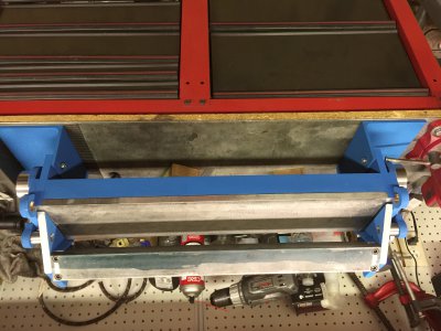
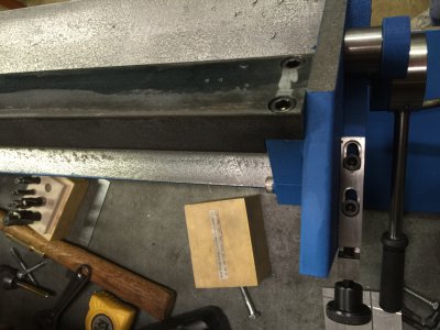
 
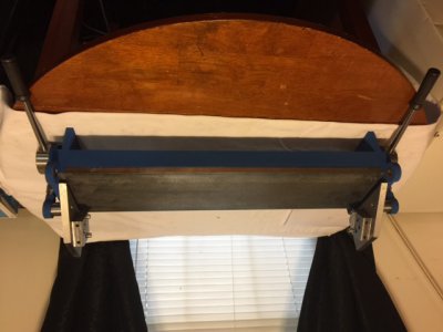
I made two feet to hold the brake. I used two pieces of 1/4" thick angle iron to make them.
image.jpeg
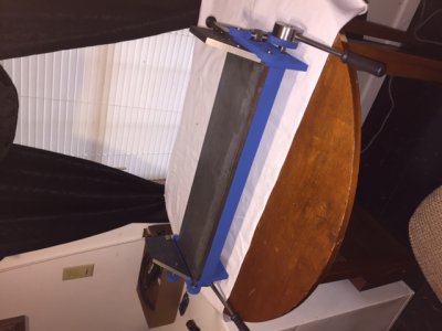
You may notice I also have installed the finger bar. It is a piece of 1" X 2" steel bar stock. This is an upgrade from the prints. The prints cal for 5/8"X 1 1/2". This one has twice the mass so I am hoping I won't need the truss as it should solve the flexing problem.
image.jpeg

Everything is coming together nicely. I have made some , I feel ,improvements by beefing up a couple areas. I tried to stick close to the prints but I may have to re make the micro adjusters because it looks like the fingers will be too far forward by almost .200". It will be an easy fix but I will wait until I get the fingers made to be sure. I believe this problem arose from the fact that the dimensions for the pivot pin hole were mising from the prints and I calculated it from some of the other prints. I may have made a boo boo in my figuring. New adjusters will fix it though if needed. The steel for the fingers will be here Saturday or Monday. I ordered cold roll for these as I don't want to fight machining the hot roll .
 
image.jpeg
I think I forgot to put in the photo of the feet I added.
Thanks Bill, it's hard taking those upside down photos.

I have no idea why the photos post upside down or sideways.
 
Last edited by a moderator:
Back
Top