

- Joined
- May 7, 2023
- Messages
- 1,338
This thread is a spin off of the following to keep things from becoming cluttered. Lathe Mill score thread.
I got this mill head in a package deal as posted in the above thread but the milling table/base was not included. Having read everything I could find about this combo and working as a toolmaker I knew I would not be happy using the Milling head attached to the lathe and was searching for a solution. I was only able to find the complete package used for $2K+ or a sold listing for the base for $1200 and I wasn't going there.
With my experience in this type of thing I knew I could not only find a good quality milling table and base, but I could also come up with a better than factory solution for the stand alone mill and do much better than mounting it to the lathe.
I had looked at a dozen different offerings and the only thing that really looked high quality out of the box was from RC machines in Germany. They have some beautiful stuff and I fell in love with this one. Its perfect! The only problem being it was going to be nearly $1100 shipped ($850 US just for the table) and they couldn't guarantee there wouldn't be import duties, so that was out.
The Base I chose was from Littlemachineshop, and it is the 5013 Mini Mill Large Table Assembly, Solid Column Base. It came well packaged in a large box containing a small wooden crate. It was securely mounted to the crate with the bolts necessary to mount it to the column for this base.
![IMG_3025[1].JPG](https://www.hobby-machinist.com/data/attachments/409/409872-74c071beae003d85eaf217775642760d.jpg "IMG_3025[1].JPG")
After unbolting it I got it together with the mill head to begin drawing up a plan to mate them together. You can see my blue pencil blueprint in the lower portion of this pic.
![IMG_3029[1].JPG](https://www.hobby-machinist.com/data/attachments/409/409877-165df7b4100b2caed3a00d33df899f4b.jpg "IMG_3029[1].JPG")
Knowing I needed to find an appropriate size chunk of steel (4"x6"x3" thick) to make this out of would take a bit of time I began working on what I felt needed attention. First up was the cleaning and adjusting of the ways and the lead screw tomb stones. These are actually the nits, but they look like littel tomb stones and are cleverly affixed by jamb screws to the base. I knew the one for the Y travel was loose from the get go as it was smooth in one direction and erratic in the other. After opening this up my thoughts were confirmed and a simple process of centering the nut with the screw and tightneing it down fixed that issue.
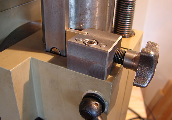
Heres the capturing method of these nuts, Y travel:
You can only see the flat end of the Y nut here, but the fixing screw head is near the bottom of the casting.
![IMG_3075[1].JPG](https://www.hobby-machinist.com/data/attachments/409/409879-e2dd9c50fe9b081b2e6b4ef4845017fe.jpg "IMG_3075[1].JPG")
And X travel.
This one came canted a bit, but it was simple to straighten out with this setup.
![IMG_3074[1].JPG](https://www.hobby-machinist.com/data/attachments/409/409880-212d4728666266771cc39057ac24d5d5.jpg "IMG_3074[1].JPG")
I do recommend disassembling and cleaning anything like this when you first get it as there is a lot of grinding dust in the works.
After disassembly and cleaning I got a good look at the fit and finish and was pleasantly surprised with the quality. Only one of each way is actually ground, but the other side is milled very finely and will act to hold oil in lieu of scraping or flaking.
There was only one small blemish in one way and overall it is really nicely made.
Here you can see the grinding dust that was still coming out after the third wipe down, there was a lot of it needing to be cleaned out.
![IMG_3082[1].JPG](https://www.hobby-machinist.com/data/attachments/409/409883-4be2c8614551f126e011d9b8d701cb3c.jpg "IMG_3082[1].JPG")
I was thrilled to find out this actually had a reasonable facsimile of an acme thread lead screw!
![IMG_3084[1].JPG](https://www.hobby-machinist.com/data/attachments/409/409884-29443002ecea60a7eed9788063ba8e88.jpg "IMG_3084[1].JPG")
Once I found my giant hunk of steel I squared it and ground it to clean it up and hogged out as much material as I could before boring the hole for the column.
![IMG_3064[1].JPG](https://www.hobby-machinist.com/data/attachments/409/409887-ce0b2ae83057e5882133fff078f11a22.jpg "IMG_3064[1].JPG")
Then I bored it to just .002 over the column diameter. This was necessary so the head can rotate for milling/drilling tall objects off of the side of the table like you would do on a B-port mill with an angle plate tied down on the table. The original base had this feature so you could swing the head out of the way when attached to the lathe, but I like the extra flexibility this offers, so I added the feature in.
![IMG_3067[1].JPG](https://www.hobby-machinist.com/data/attachments/409/409888-032b6ba05b3943ca508b1e560374546d.jpg "IMG_3067[1].JPG")
I don't like having the mill table that cluttered and disorganized, but I had to fit this in with other work so I was running two machines at the same time and generally making a huge mess.
Bored and relieved on the top edge.
![IMG_3069[1].JPG](https://www.hobby-machinist.com/data/attachments/409/409889-8f5cfe10283575bdd6b70989e42e400d.jpg "IMG_3069[1].JPG")
I milled a 1/8" cosmetic relief slot to hide the saw cut I needed to make so it would clamp to the column. This way the rough saw cut is hidden to all but the most discerning eyes.
![IMG_3070[1].JPG](https://www.hobby-machinist.com/data/attachments/409/409890-e920d8b096a5f8c104479d7059ba2ac9.jpg "IMG_3070[1].JPG")
I got this mill head in a package deal as posted in the above thread but the milling table/base was not included. Having read everything I could find about this combo and working as a toolmaker I knew I would not be happy using the Milling head attached to the lathe and was searching for a solution. I was only able to find the complete package used for $2K+ or a sold listing for the base for $1200 and I wasn't going there.
With my experience in this type of thing I knew I could not only find a good quality milling table and base, but I could also come up with a better than factory solution for the stand alone mill and do much better than mounting it to the lathe.
I had looked at a dozen different offerings and the only thing that really looked high quality out of the box was from RC machines in Germany. They have some beautiful stuff and I fell in love with this one. Its perfect! The only problem being it was going to be nearly $1100 shipped ($850 US just for the table) and they couldn't guarantee there wouldn't be import duties, so that was out.
The Base I chose was from Littlemachineshop, and it is the 5013 Mini Mill Large Table Assembly, Solid Column Base. It came well packaged in a large box containing a small wooden crate. It was securely mounted to the crate with the bolts necessary to mount it to the column for this base.
After unbolting it I got it together with the mill head to begin drawing up a plan to mate them together. You can see my blue pencil blueprint in the lower portion of this pic.
Knowing I needed to find an appropriate size chunk of steel (4"x6"x3" thick) to make this out of would take a bit of time I began working on what I felt needed attention. First up was the cleaning and adjusting of the ways and the lead screw tomb stones. These are actually the nits, but they look like littel tomb stones and are cleverly affixed by jamb screws to the base. I knew the one for the Y travel was loose from the get go as it was smooth in one direction and erratic in the other. After opening this up my thoughts were confirmed and a simple process of centering the nut with the screw and tightneing it down fixed that issue.
Heres the capturing method of these nuts, Y travel:
You can only see the flat end of the Y nut here, but the fixing screw head is near the bottom of the casting.
And X travel.
This one came canted a bit, but it was simple to straighten out with this setup.
I do recommend disassembling and cleaning anything like this when you first get it as there is a lot of grinding dust in the works.
After disassembly and cleaning I got a good look at the fit and finish and was pleasantly surprised with the quality. Only one of each way is actually ground, but the other side is milled very finely and will act to hold oil in lieu of scraping or flaking.
There was only one small blemish in one way and overall it is really nicely made.
Here you can see the grinding dust that was still coming out after the third wipe down, there was a lot of it needing to be cleaned out.
I was thrilled to find out this actually had a reasonable facsimile of an acme thread lead screw!
Once I found my giant hunk of steel I squared it and ground it to clean it up and hogged out as much material as I could before boring the hole for the column.
Then I bored it to just .002 over the column diameter. This was necessary so the head can rotate for milling/drilling tall objects off of the side of the table like you would do on a B-port mill with an angle plate tied down on the table. The original base had this feature so you could swing the head out of the way when attached to the lathe, but I like the extra flexibility this offers, so I added the feature in.
I don't like having the mill table that cluttered and disorganized, but I had to fit this in with other work so I was running two machines at the same time and generally making a huge mess.
Bored and relieved on the top edge.
I milled a 1/8" cosmetic relief slot to hide the saw cut I needed to make so it would clamp to the column. This way the rough saw cut is hidden to all but the most discerning eyes.
Last edited:
![IMG_3027[1].JPG](https://www.hobby-machinist.com/data/attachments/409/409892-3a8a24de6f51683adcb2d3490d8961b1.jpg "IMG_3027[1].JPG")
![IMG_3028[1].JPG](https://www.hobby-machinist.com/data/attachments/409/409893-385810688a96e6fad47486125aae8c55.jpg "IMG_3028[1].JPG")
![IMG_3071[1].JPG](https://www.hobby-machinist.com/data/attachments/409/409894-469c080331608908344d15b219912012.jpg "IMG_3071[1].JPG")
![IMG_3072[1].JPG](https://www.hobby-machinist.com/data/attachments/409/409895-0dfdacda2fb3ab8c6f34ad01f14dcda3.jpg "IMG_3072[1].JPG")
![IMG_3073[1].jpg](https://www.hobby-machinist.com/data/attachments/409/409900-e3c55784a4dad3a3bdcc19e28b944481.jpg "IMG_3073[1].jpg")
![IMG_3076[1].JPG](https://www.hobby-machinist.com/data/attachments/409/409901-b62819d052b9c4336cfa3900db66ea9c.jpg "IMG_3076[1].JPG")
![IMG_3077[1].JPG](https://www.hobby-machinist.com/data/attachments/409/409902-8dd2469d1d6e7b3925e21e22e3ab79cb.jpg "IMG_3077[1].JPG")
![IMG_3078[1].JPG](https://www.hobby-machinist.com/data/attachments/409/409903-55338068011336d120d56197b3ec61cd.jpg "IMG_3078[1].JPG")
![IMG_3086[1].JPG](https://www.hobby-machinist.com/data/attachments/409/409904-aafcff1af816a237f8b46c6138bbd0a8.jpg "IMG_3086[1].JPG")
![IMG_3085[1].JPG](https://www.hobby-machinist.com/data/attachments/409/409905-fb10f97ee7e56c2bdea3221cc35c9179.jpg "IMG_3085[1].JPG")
![IMG_3090[1].JPG](https://www.hobby-machinist.com/data/attachments/410/410099-507061726ac93c85d6981cb2121215f5.jpg "IMG_3090[1].JPG")
![IMG_3091[1].JPG](https://www.hobby-machinist.com/data/attachments/410/410100-28bf4783ac8baa4d66f074db90dc967f.jpg "IMG_3091[1].JPG")
![IMG_3092[1].JPG](https://www.hobby-machinist.com/data/attachments/410/410101-f0132873392ca7ae276919a92172c4ae.jpg "IMG_3092[1].JPG")
![IMG_3093[1].JPG](https://www.hobby-machinist.com/data/attachments/410/410102-546b9bfdf71fefa13965188926512b96.jpg "IMG_3093[1].JPG")
![IMG_3094[1].JPG](https://www.hobby-machinist.com/data/attachments/410/410103-c470d0d2940087ee5a8973d53bed5428.jpg "IMG_3094[1].JPG")
![IMG_3102[1].JPG](https://www.hobby-machinist.com/data/attachments/410/410106-2c9b2ea1da9c00db97858aea54029944.jpg "IMG_3102[1].JPG")
![IMG_3100[1].JPG](https://www.hobby-machinist.com/data/attachments/410/410105-01bcf79ce345b93d30da8ba5e8155690.jpg "IMG_3100[1].JPG")
![IMG_3095[1].JPG](https://www.hobby-machinist.com/data/attachments/410/410104-229a0b7b3015442c210390d05348e510.jpg "IMG_3095[1].JPG")
![IMG_3103[1].JPG](https://www.hobby-machinist.com/data/attachments/410/410107-a512560671749e9b246c3f15677de5ad.jpg "IMG_3103[1].JPG")
![IMG_3114[1].JPG](https://www.hobby-machinist.com/data/attachments/410/410161-4ec228eb7d1e9985774eee9d88bfbfa7.jpg "IMG_3114[1].JPG")
![IMG_3105[1].JPG](https://www.hobby-machinist.com/data/attachments/410/410162-16cc9b577054b915e4e9ece3d5c3877b.jpg "IMG_3105[1].JPG")
![IMG_3106[1].JPG](https://www.hobby-machinist.com/data/attachments/410/410163-8c2dd0d2b36babce4be832ec3cf0ccdd.jpg "IMG_3106[1].JPG")
![IMG_3111[1].JPG](https://www.hobby-machinist.com/data/attachments/410/410164-37b0a9e892869f0c03180c646d671ffd.jpg "IMG_3111[1].JPG")
![IMG_3113[1].JPG](https://www.hobby-machinist.com/data/attachments/410/410165-35b89a05921495adb753c9f2185b7d8a.jpg "IMG_3113[1].JPG")
")
![IMG_3132[1].JPG](https://www.hobby-machinist.com/data/attachments/410/410367-42aab42907254885ce746bc3ecca8192.jpg "IMG_3132[1].JPG")
![IMG_3133[1].JPG](https://www.hobby-machinist.com/data/attachments/410/410368-a336f52cbf8e6161a8b7dae72ae2d6e1.jpg "IMG_3133[1].JPG")
![IMG_3135[1].JPG](https://www.hobby-machinist.com/data/attachments/410/410370-8199b556f26470f1aa41f2f209f4a0fb.jpg "IMG_3135[1].JPG")
![IMG_3136[1].JPG](https://www.hobby-machinist.com/data/attachments/410/410371-2a9dccc7852470df7a15be975971154e.jpg "IMG_3136[1].JPG")
![IMG_3148[1].JPG](https://www.hobby-machinist.com/data/attachments/410/410631-7f92991da7223a879e6a4ff71eea4d26.jpg "IMG_3148[1].JPG")
![IMG_3180[1].JPG](https://www.hobby-machinist.com/data/attachments/411/411374-47f77764b12258ad63f8a6e5604a7bc9.jpg "IMG_3180[1].JPG")
![IMG_3181[1].JPG](https://www.hobby-machinist.com/data/attachments/411/411375-b9c83f4b54d4c85f325885efcc56e033.jpg "IMG_3181[1].JPG")
![IMG_3182[1].JPG](https://www.hobby-machinist.com/data/attachments/411/411376-b88ea4e0a77b487d39453fd11f671df4.jpg "IMG_3182[1].JPG")
![IMG_E3184[1].JPG](https://www.hobby-machinist.com/data/attachments/411/411388-1656f1c411b0caf73ac40fd44de20d94.jpg "IMG_E3184[1].JPG")
![IMG_3186[1].JPG](https://www.hobby-machinist.com/data/attachments/411/411378-490e38ed4beafc6b3b2032fe9a6f4b1b.jpg "IMG_3186[1].JPG")
![IMG_3187[1].JPG](https://www.hobby-machinist.com/data/attachments/411/411379-b2e1760528122db6f56caf015afd8912.jpg "IMG_3187[1].JPG")
![IMG_3188[1].JPG](https://www.hobby-machinist.com/data/attachments/411/411380-c83c9628afd73c3fe615e7ea68d6ac54.jpg "IMG_3188[1].JPG")
![IMG_3189[1].JPG](https://www.hobby-machinist.com/data/attachments/411/411381-d14e23bfaf4754c8a8cd1d575e71f036.jpg "IMG_3189[1].JPG")
![IMG_3190[1].JPG](https://www.hobby-machinist.com/data/attachments/411/411382-deeac6a530a2b3ec1f41808ac601a1f9.jpg "IMG_3190[1].JPG")
![IMG_3184[1].JPG](/data/attachments/411/411377-87cd8f163d85e12191bc8b67efb1b680.jpg)