Prazi BFE65-Littlemachineshop Big Mill table Frankenbuild, spin off thread.

You are lucky that you are still around. You might consider putting a bleed resistor across the run cap. Capacitors can store enough energy to kill and always should be considered charged unless you discharge it. All my "dangerous" caps are stored with a short between the terminals, because they can pickup charge in unexpected ways. They get placed in circuit and then are unshorted. Nearly all my designs have bleeders. Like you, I learned after getting shocked. A bleeder is a very high value resistance and will slowly discharge the cap, without affecting the circuit performance. I aim for a 10 second discharge, roughly.
Yeah, the potential is there but it’s not my first rodeo and I had one hand behind my back. Pinky touched the pliers putting the terminal on and the jolt went through my fingers.

Way back in the long ago when I started working factory jobs we had a motor assembly area with literal pallets of start caps for AC units.

Every time a new guy got put in that area someone would wait till they were away and take a cord with both leads stripped, plug it in and charge random caps in the skid.

Holy hell the noises people made.

Right of passage as dumb as it was. What was funnier was watching the last guy to get it come in or back from break and gingerly short all of the caps for the next few weeks.

This was the mid 80s when pranking on the shop floor was still a thing.
 
Good to know. Was kind of a public service announcement. Any HV caps should be treated with caution. One arm behind the back is good practice, since it helps prevent a through the heart shock which can be fatal. (With enough energy.)

Think it only takes on the order of 0.1J of energy to be fatal, where E = 1/2 C*V*V, where C is in farads and V is in volts. If you are dealing with high voltage it doesn't take much capacitance to become dangerous.
65 millamps is what I was taught.


Got a few things done while waiting for my scales.

First is a quill light. I have a fluorescent light above the machine, but the head is kinda big and blocky so the vise is in shadow. I got some "Angel eyes" from ebay for this and if I remember correctly their 90mm.

Made an aluminum ring to fit them in and added magnets to secure it. Took the magnets off immediatly as it was making things magnetized that I would prefer to not have magnetized, so I stuck them on with gorilla double sided tape.


Up from under the neath.

IMG_3236[1].JPG


Ooooh, Shiny!!


IMG_3240[1].JPG


Before:


IMG_3238[1].JPG


And after, much better!


IMG_3239[1].JPG


I also fabbed up a set of wrenches for the ER20 collet chuck.

Got a lil carried away with the detailing, but I think they look great and their much lighter than before all the fancy work.

3/8" thick O-1 steel.

IMG_3233[1].JPG


I got a new tablet for the T-DRO and the T-DRO glass scale adapter and my scales just cleared customs so they should be here within a week.

Then I get the joy of disassembling this to do a bunch of upgrades, which reminds me, I should make a list.
 
Scales hit my doorstep yesterday and I immediately started cutting them up. I had a choice between a scale that had juuust enough travel and one that was a lil longer but would need to possibly be trimmed and I went with the latter.

I could have made it work as it was, but that’s not me. I needed to trim the X scale .310 to make it the same length as the mill table minus the end plates. This is important as I’ll be making my own end plates to suit the plans I have for the power feed and controls.

Measured once and cut twice. The scale extrusion was the gummiest thing this side of oxygen free copper and sucked just a bit to work with, but I got it done.

Here I had already milled it to length and I’m drilling the new screw holes.

Do not touch the glass!


IMG_3243.jpeg


Once that was done and deburred, and deburred again and again (did I mention this stuff was gummy?) I cut clearance in the end mounting blocks to clear the glass scale. I have at least .030 all around so that should be fine.

This is Zamak and milled real nice.

IMG_3244.jpeg


The wipers needed trimming next and it’s important to note they need to be 3/32ish longer than the cover to index into a slot in the end cap and seal properly.


Bad pic, but you can make out the overhang and the slot the wipers go into.

IMG_3249.jpeg


After that came a final cleaning and inspection for foreign bodies (there was a chip inside from the factory) and assembly.

Nice and clean.


IMG_3251.jpeg


And all put back together.


IMG_3254.jpeg

That fingerprint bugs me, too late now.
 
Got the mill torn completely apart in order to install the scales and while it is apart I figured I would check the base and column mount for square.

Put it on the surface plate and checked it out and found it to be off here and there, especially where the column mounts are. This jibed with how I had to shim the column, even though it did net seem to account for the entirety of the amount of shim needed. Still a step in the right direction.


The bottom of the base was wonky, not that it matters to the function of the mill, but I had to true this up so I could flip it and grind the column mounting pads.


Came to a touch on one corner and had to take .004-.005 to get all four corners true.


IMG_3324.jpeg


After a couple passes.

IMG_3344.jpeg

All cleaned up.


IMG_3345.jpeg


After I flipped it to do the pads I first blued them and came to a touch on the highest one.


IMG_3348.jpeg

And they cleaned up with about .003 taken off.


IMG_3349.jpeg


Now that this is taken care of I can work on installing the scales and reassembly of the base.
 
Between days doing the larger work in the shop I found a couple of things on the table/base that I thought needed addressed.

First up was the table lock screws. These were nice indexing handle type units, but they were hideously long and looked like they could get in the way or broken so I shortened them on the lathe.


As delivered:


View attachment 452659


And drastically shortened.


View attachment 452660


Much better. I did this to both the X and Y locks and decided the X needed a second lock on the opposite side so the table will not twist when the single lock was tightened, so I ordered one from LMS to be installed. The Y lock was centered in the gib so I figured that one was fine.


Back in the shop I finished the cosmetic slot going across the top and down the edge where the saw cut was to go, and began drilling the holes to mount it to the mill table. I had to leave the saw cut for last to ensure everything stayed square and rigid for the rest of the steps to be performed.


View attachment 452661

After the mounting holes were finished I cut the front corner on a 45* angle to give it a nicer and more factory look. I hesitated on this as I wanted as much rigidity and especially mass in the machine as possible, but in the end this piece came out to 20lbs of solid steel VS 3lbs of cast aluminum on the factory part its replacing.


Should be more than good enough.


View attachment 452662


In the above pic it was setup to be milled flat, then was later ground to match the rest of the surfaces.

At this point I brought it home and mated it up with the base. Any miscalculations would be discovered at this stage before going any further and possibly needing to scrap the whole works, but everything fit perfectly. That was a nice surprise as I only had .004 clearance on the bolt holes.


View attachment 452667


Next up was the threaded and bored clamping bolt holes. I drilled and tapped for M8-1 bolts using fine threads to increase the clamping forces.


View attachment 452668


I counter bored these holes so the head of the cap screws would stand slightly proud of the surface so they would be easy to feel from the front of the machine to loosen/tighten with a wrench until I can make some factory style locking levers similar to what's on the vertical clamping lock for the head.

Here I have it in position to tap the holes. I made the counter bores large enough to accept the tap handle jaws as to allow the maximum thread depth for increased longevity of the threads.

View attachment 452669


Then the final step was the saw cut.


View attachment 452670


After the saw cut was done I sandblasted the whole thing to hide my sins give it a good surface for paint to adhere to.

And with that finished I put it together and everything looked fine and worked well, then the doorbell rang.

My vise was here just at the perfect moment.

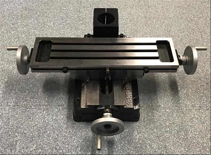
All together and (Mostly) ready to go.


View attachment 452671


Cute, isn't it?


View attachment 452672

I ordered a 3" vise as I wasn't sure how much it would stick off the back of the table or the quality of the brand, but there's more than enough room and the vise is nice enough, so Ill probably order the same vise in 4" as the 3" seems just a tad small. The 4" is also almost twice the weight so it will help with the mass equation.

Just need my clamping bolts and the ER-20 collet chuck and collets to show up and I can start to use it.
Looks really nice, I have the exactly same little mill and you save me som time on the hunt for a good
Thanks John, this is really fun.

Im trying for what may be the first time in my life to set this all up properly from the beginning. I'm setting this up in our generator room that has acted as a make shift work shop/hobby room for years, and had become somewhat of an underutilized cluttered mess. I had a compressor, bandsaw, belt sander and small drill press down there for years, but honestly much of that was bought to fill a niche or were cast offs from the neighbors.

Putting stuff in a room for occasional use is one thing, building that all into a well thought shop is a bit different.

Example, I spent an hour last night getting my blow guns throttled down to a reasonable level for this small space. Blasting chips over my head and down my pants was sub optimal and kicked up too much residual dust.

This is the space I'm working with. I'm still trying to get rid of some of the "Legacy" stuff (Read mess) and free up space, but that needs to go somewhere and will take time. There are probably 10RC boats and 3-4 RC Helicopters in this room along gunsmithing supplies and other ephemera.


View attachment 452928


I want to get both machines (Mill and Lathe) on one side at one end of the room to try and keep all of the chips away from the entry/exit to lessen migration into the living space, so everything is constantly getting moved as time and supplies permit. As to supplies, I installed a dehumidifier (White thing behind the bandsaw) which needs a constant on plug on the power strip. Thanks to an A-Zon supplier who couldn't get their **** together it took me 4 weeks to get this. The power strip is perfect, but the time to acquire it.....

Moving on, I completed my first project on the mill.


View attachment 452929


Nothing much, but I'm still getting used to not having a DRO on this and the overall response of the machine to inputs. Plus Im still waiting on the threaded rod to make a drawbar.

This is a T handle for the lathe tool holders with a replaceable Allen key. I made one for the lathe at work and everyone loved it and it does make tool changes much easier than a plain Allen wrench or a plastic handled T wrench. The plastic handle wrenches are nice, but they seem to fail too often under shop conditions and are costly to replace.

It goes here.


View attachment 452930


Since I'm waiting on parts I decided to work on taming the way covers. The amount of way cover material they give you with these seems excessive and I hadn't had this table for one day until I started bending the thin metal bars that attached them with from the factory. I made new bars out of 5/32 O-1 and shortened the covers by a few inches.


Looks and works much better.


View attachment 452931


And now it doesn't balloon all over when fully compressed.


View attachment 452932


In that pic you can see the poorly fitted clamping screws. I intended these to be temporary until I can make proper handles, but the bolt length needed and the amount of thread on those didn't line up with my plans, so they stick out.
Nice build, I have the exact same little mill and now you save me some time to search for a base table


Christer
 
Looks really nice, I have the exactly same little mill and you save me som time on the hunt for a good

Nice build, I have the exact same little mill and now you save me some time to search for a base table


Christer
Hello Christer!

While this was the best option I could find this side of the world, here's something I would have gone with if shipping were possible.


I cant guarantee this is a good fit as I haven't seen it first hand, but it looks a little better finished (For the price it should be!) and given the weight seems to have more mass.

Just throwing this out there as its much closer to you than an LMS delivery.

Let me know if you have any questions.
 
It was not so easy to order that one, but i give it a try.
I hope that i get it
 
Got the scales mounted and Touch DRO up and running.

The only tricky part was for the Y scale as these is no room to mount it conventionally, so it needs a rail to ride on for much of its length.

I didn't take many pics of the mounting process as it was a mount/measure/remove/take to work and modify/wash rinse repeat, type ordeal as I couldn't use the mill its self as it was torn apart for this.

Front view.

IMG_3366[1].JPG


Back end view.


IMG_3365[1].JPG


And as these things go, I had to move the way cover mounting holes up to clear the scales.


IMG_3364[1].JPG


The rail the scale extrusion rides on is mounted to the saddle via the two 4mm screws provided by the factory and a third I added in between them. These are all on one end of the rail and the rail and scale travel past the column mount on the left side of the machine. A bit odd to my way of thinking but effective and rigid enough.


Here's a video of the LMS system being installed and watching this even though its similar to the T-DRO, Im glad I went with the glass scales and T-DRO as I'm sure this is a superior system and was cheaper even with the purchase of a new tablet to run the software.


LMS wants $475 for the two axis magnetic scale kit without the tablet. I spent $420 total with tablet, glass scales and the Touch DRO scale converter. That's roughly $160 difference for a better system, and though it did take some sweat equity, I didn't lose any travel on either axis as it seems the LMS system would judging by the above video. The reviewer seems to be going off of LMS's included instructions and looses 1 3/8" due to the way they have you mount the reader head which in my mind is unacceptable. You could easily reorient the scales, but it looks like even then you would lose some valuable travel.

My mill is all back together now and the scales are calibrated. Calibrating the T-DRO was a snap. Took a little fiddling to get it "Perfect" and I'm only out by .0002 over 4" on the Y and dead nuts on the X so Id say that's near perfect for this machine.

The Y axis is a little stiff at the extreme of travel I needed in order to use the 4" Jo block I did the setup with, which may have affected things a bit. I set it so if anything it would cut .0002 short as you can always take more off if needed.

Overall very happy with the setup even if it did take me much longer than anticipated.
 
Last edited:
Had some time today to work on the ring light and get that sorted out.

I initially just threw it on as a kind of proof of concept powered by a 11.7V lithium battery from one of my helicopters, just to see if I liked it. With that worked out I decided to make it neat and self contained like it was something professionally made vs a bunch of random stuff stuck together.

I was able to match this up with an old wall wart for power which made for a simple, neat arraignment over the battery setup.

Next I was able to find a suitable plastic box to house the components on Amazon and started fitting the components into it. Started by finding a good location for the switch and drilling the proper size hole.

I used one of my custom fishtail drills for this and had excellent results.

Thread on those here. https://www.hobby-machinist.com/threads/hand-sharpening-fishtail-drills-a-brief-primer.106376/


This type of drill was chosen as the sides of the box are tapered and this drill grind has excellent centering abilities as you can see in this pic.


IMG_3409.JPG


Its cutting about half way through here on one side with the other side not even touching and staying perfectly centered.

Makes a nice hole with no chance of shattering or cracking the plastic, and the center breaks out in one piece.


IMG_3410.JPG


Then I fitted the switch and saw there was room inside for the constant current converter in there if I took that out if its case.

Here you can see the box with the switch installed, the CC converter (one in its case and one without the case), big difference in size without the case.


IMG_3414.JPG


Then all I had to do was fit it all into the case and solder it up. I put a dab of liquid electrical tape on the CC module to stick it to the side of the case. Now I just need to let that dry overnight and I can install the whole works.


IMG_3417.JPG


And here's the whole light system finished and ready to install.

The brass tube that protects the wires looks like a demented Childs art project, but it needs the bends to make it so its up and out of the way.


light.JPG


And everything put in place with double sided gorilla tape and pliobond glue to hold the tube in place. Pliobond is a rubbery glue that is great for odd shaped or hard to glue pieces and it remains flexible (Hence the name) and can be removed easily. Good stuff.


IMG_3421[1].JPG


And here is the switch from the side and from the front, nicely tucked away yet easy to reach.


IMG_3431[1].JPG

IMG_3432[1].JPG
 

Attachments

  • IMG_3412.JPG
    IMG_3412.JPG
    484.4 KB · Views: 2
Last edited:
Back
Top