- Joined
- May 7, 2023
- Messages
- 1,335
All righty then, Now all I have left to do is everything.
Now that the scales and the light are finalized Ill be turning my attention to the power feed.
I have an idea of what I want, but I'm not sure how far I can take it with the items at hand. I know I want it to be Bridgeport like in layout and function, I'm just not sure until I really get into it how close I can get.
I started out by making the right hand side of the mill table in accordance with my plan. I started out with a hunk of steel 4.75x4x2". I know what I want is inside it, I just need to remove everything that is not the finished product and what's left will be the finished part. I'm purposely making it bigger than it will probably wind up in its finished state, just so I have enough material to make my idea work, and because I may also come up with a few more ideas along the way.
First off I located and drilled 3 holes copied from the original part on the mill table. I thought I had pics of this, but you'll have to use your imagination. Once I had the holes drilled (After squaring and bringing the block to size.) I began hogging out the unnecessary bits with a 1.5"carbide shell mill.
Somewhere along the line I also set up the rotary table and bored out the bearing pockets similar to what is in the factory end plate, but I apparently didn't take pictures of that either. I know I had done this previously because you can see it in these pics. It was a good amount of work with one side being 1"x.480 and the other being 1"x1.300 deep. Just pretend I showed you as there was not much to see as the action was deep in a pocket.
I started milling the wider parts that needed to be removed as to save time and reduce having to go over the different cuts more than once, or biggest to smallest if you will.
![IMG_3391[1].JPG IMG_3391[1].JPG](https://www.hobby-machinist.com/data/attachments/416/416884-0d9a15362257fd9b63adcc0f7fdcc856.jpg)
Then I went at the smaller section with a 3/4" endmill.
![IMG_3392[1].JPG IMG_3392[1].JPG](https://www.hobby-machinist.com/data/attachments/416/416885-f36b4f83dad8e8b81eaa67df208de5cf.jpg)
Then once I had my "Island" roughed out, I went back to the rotary table and began milling the island to size.
First with a standard endmill,
![IMG_3393[1].JPG IMG_3393[1].JPG](https://www.hobby-machinist.com/data/attachments/416/416886-f3feca8ee1f7dc848f7baa6485c4f060.jpg)
![IMG_3395[1].JPG IMG_3395[1].JPG](https://www.hobby-machinist.com/data/attachments/416/416887-24b8fb7faa3de4a7c13b89774fbea280.jpg)
Then with a 3/32? radiused end mill for the final shape and size. You can see the bluing showing where Im just about .010 away from the final finish diameter here.
![IMG_3397[1].JPG IMG_3397[1].JPG](https://www.hobby-machinist.com/data/attachments/416/416890-ecd7c57744714805a3a676b40820b0a5.jpg)
Once that was all done I realized I had a problem, none of the four roughing cuts from earlier wound up at the same height? Depth? Whatever, so I decided to keep it in the rotary table and take a .010 cleanup cut making a circular pattern across the whole part.
![IMG_3400[1].JPG IMG_3400[1].JPG](https://www.hobby-machinist.com/data/attachments/416/416888-d51d3fd97253557497a0b0d03f593d09.jpg)
This was kinds time consuming/difficult/annoying as I had to stop every quarter turn to move a clamp. Speaking of turns, did I mention how many damn times I had to turn the handwheel on the rotary table up to this point? I'm thinking somewhere in the neighborhood of 500 revs to finish it. I would have done the math but I was too tired once I thought about this.
But the end result turned out nice.
![IMG_3402[1].JPG IMG_3402[1].JPG](https://www.hobby-machinist.com/data/attachments/416/416889-56b95032f85b4a51c13760209410cc1f.jpg)
Hey lookit! My one hold down clamp is all catawampus.
I hate that.
Now that the scales and the light are finalized Ill be turning my attention to the power feed.
I have an idea of what I want, but I'm not sure how far I can take it with the items at hand. I know I want it to be Bridgeport like in layout and function, I'm just not sure until I really get into it how close I can get.
I started out by making the right hand side of the mill table in accordance with my plan. I started out with a hunk of steel 4.75x4x2". I know what I want is inside it, I just need to remove everything that is not the finished product and what's left will be the finished part.
First off I located and drilled 3 holes copied from the original part on the mill table. I thought I had pics of this, but you'll have to use your imagination. Once I had the holes drilled (After squaring and bringing the block to size.) I began hogging out the unnecessary bits with a 1.5"carbide shell mill.
Somewhere along the line I also set up the rotary table and bored out the bearing pockets similar to what is in the factory end plate, but I apparently didn't take pictures of that either.
 I know I had done this previously because you can see it in these pics. It was a good amount of work with one side being 1"x.480 and the other being 1"x1.300 deep. Just pretend I showed you as there was not much to see as the action was deep in a pocket.
I started milling the wider parts that needed to be removed as to save time and reduce having to go over the different cuts more than once, or biggest to smallest if you will.
![IMG_3391[1].JPG IMG_3391[1].JPG](https://www.hobby-machinist.com/data/attachments/416/416884-0d9a15362257fd9b63adcc0f7fdcc856.jpg)
Then I went at the smaller section with a 3/4" endmill.
![IMG_3392[1].JPG IMG_3392[1].JPG](https://www.hobby-machinist.com/data/attachments/416/416885-f36b4f83dad8e8b81eaa67df208de5cf.jpg)
Then once I had my "Island" roughed out, I went back to the rotary table and began milling the island to size.
First with a standard endmill,
![IMG_3393[1].JPG IMG_3393[1].JPG](https://www.hobby-machinist.com/data/attachments/416/416886-f3feca8ee1f7dc848f7baa6485c4f060.jpg)
![IMG_3395[1].JPG IMG_3395[1].JPG](https://www.hobby-machinist.com/data/attachments/416/416887-24b8fb7faa3de4a7c13b89774fbea280.jpg)
Then with a 3/32? radiused end mill for the final shape and size. You can see the bluing showing where Im just about .010 away from the final finish diameter here.
![IMG_3397[1].JPG IMG_3397[1].JPG](https://www.hobby-machinist.com/data/attachments/416/416890-ecd7c57744714805a3a676b40820b0a5.jpg)
Once that was all done I realized I had a problem, none of the four roughing cuts from earlier wound up at the same height? Depth? Whatever, so I decided to keep it in the rotary table and take a .010 cleanup cut making a circular pattern across the whole part.
![IMG_3400[1].JPG IMG_3400[1].JPG](https://www.hobby-machinist.com/data/attachments/416/416888-d51d3fd97253557497a0b0d03f593d09.jpg)
This was kinds time consuming/difficult/annoying as I had to stop every quarter turn to move a clamp. Speaking of turns, did I mention how many damn times I had to turn the handwheel on the rotary table up to this point? I'm thinking somewhere in the neighborhood of 500 revs to finish it. I would have done the math but I was too tired once I thought about this.
But the end result turned out nice.
![IMG_3402[1].JPG IMG_3402[1].JPG](https://www.hobby-machinist.com/data/attachments/416/416889-56b95032f85b4a51c13760209410cc1f.jpg)
Hey lookit! My one hold down clamp is all catawampus.
I hate that.
Last edited:


![IMG_3458[1].JPG IMG_3458[1].JPG](https://www.hobby-machinist.com/data/attachments/417/417902-03e27ce79222615046e5c29d1858589e.jpg)
![IMG_3461[1].JPG IMG_3461[1].JPG](https://www.hobby-machinist.com/data/attachments/417/417903-1f2bc63b01c210c44b04c8372332a148.jpg)
![IMG_3467[1].JPG IMG_3467[1].JPG](https://www.hobby-machinist.com/data/attachments/417/417904-9fcd24e1406b6d02ed397654a0b0fd49.jpg)
![IMG_3469[1].JPG IMG_3469[1].JPG](https://www.hobby-machinist.com/data/attachments/417/417905-8542e1ff9eaf39905fe0c0ae208a0de6.jpg)
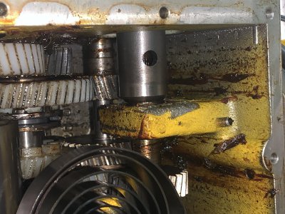
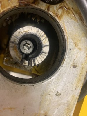
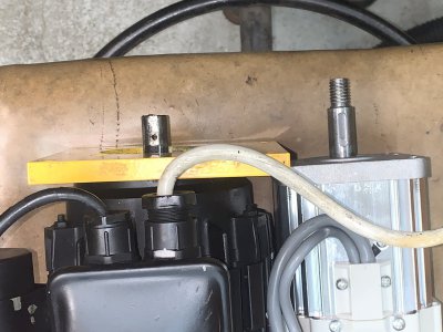
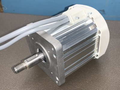
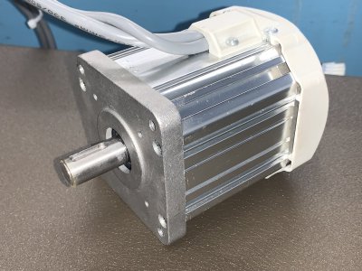
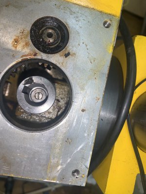
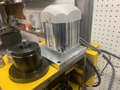
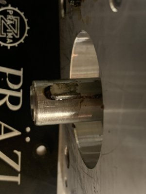
![IMG_4090[1].JPG IMG_4090[1].JPG](https://www.hobby-machinist.com/data/attachments/440/440292-5e47228352412ca824a84aa7fe7fad99.jpg)
![IMG_4157[1].JPG IMG_4157[1].JPG](https://www.hobby-machinist.com/data/attachments/441/441579-a363d4cc8cf6e914c8eb4fa38a34b17b.jpg)
![IMG_4158[1].JPG IMG_4158[1].JPG](https://www.hobby-machinist.com/data/attachments/441/441580-b7a47c743646c501185d1b9834feed04.jpg)
![IMG_4160[1].JPG IMG_4160[1].JPG](https://www.hobby-machinist.com/data/attachments/441/441583-913cc68c0dcf0381fce06d82dcee15dc.jpg)
![IMG_4161[1].JPG IMG_4161[1].JPG](https://www.hobby-machinist.com/data/attachments/441/441585-3baf2ee60987f13929acb8e91f6d4587.jpg)
![IMG_4159[1].JPG IMG_4159[1].JPG](https://www.hobby-machinist.com/data/attachments/441/441582-6fd1c7aadd96583c8bee1b3201d95ad4.jpg)