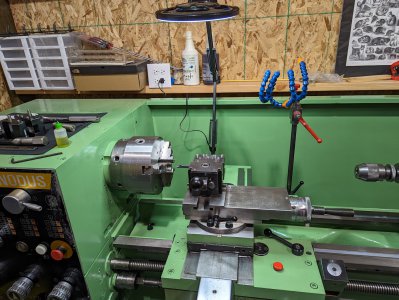
Does this machine have a rack on the underside of the ways for driving the carriage? That sounds like there could be a tooth missing on the rack if it only happens at that point. If it was the gear, I would expect it to happen elsewhere as well.
-
Welcome back Guest! Did you know you can mentor other members here at H-M? If not, please check out our Relaunch of Hobby Machinist Mentoring Program!
You are using an out of date browser. It may not display this or other websites correctly.
You should upgrade or use an alternative browser.
You should upgrade or use an alternative browser.
Project: My "Big Nards" - Nardini Nodus 1760 Lathe
- Thread starter pontiac428
- Start date
- Joined
- Apr 23, 2018
- Messages
- 6,830
Yes it does, and that is a good point. The rack itself is in great shape (dog knows I spent enough time scrubbing it with a toothbrush), but at no point could I make a visual inspection of the pinion drive gear. With the drive out, the handwheel has no play or excessive backlash- the handwheel scale is based on 125 mm/revolution, and my actual backlash is less than .020 on long traverse. My gut is really telling me it's the internal hex driven by the shaft. The only way to really see it will be to remove the compound, cross, and saddle, then the bearing block and shafting. Not hard, but unplanned and necessary.
That saddle is gonna be over my lifting capacity. Now I need to source M10 threaded eye hooks so I can use el hoisto.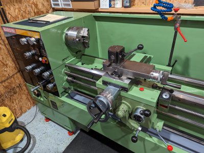
That saddle is gonna be over my lifting capacity. Now I need to source M10 threaded eye hooks so I can use el hoisto.

I realized after posting that if the hand wheel works there, it probably isn’t the rack. Kind of hard diagnosing from 3,000 miles away . One other thought, and then I am out of suggestions, have you run an indicator along the drive shaft? I’m wondering if it is bent at that point if it would pull the drive gear out of alignment enough that it will no longer drive the carriage, but by hand might still work if that uses a different gear to drive it.
- Joined
- Apr 23, 2018
- Messages
- 6,830
That was actually my first thought. Yes, somewhere in trucking and handling, the shaft did get bent. It hops a bit as it gets closer to the head, and you can see misalignment being straightened by the skirt's pass-through holes as you traverse. The carriage's lurch/creep behavior as the drive connection is broken coincides with an increase in misalignment of the shaft. Overall, the shaft may only be 1/2" out of straight, but it appears to be concentrated near the headstock.
I have a lead screw/drive shaft support that I moved around trying to get a straighter shot for the shaft to rotate about. I tried it on both sides of the carriage, and it didn't help.
The shaft will probably need to be straightened with a hydraulic press and v-blocks. It feels like spring steel trying to move it by hand. It's not mangled and the hexagon corners are crisp, so whatever is worn must be wallowed out pretty bad. Looking at the exploded diagram, the parts are well-constrained, it doesn't seem like there is much wiggle room to intermittently break gear contact. The carriage just starts moving weakly then stops without any gear popping or deflection. Along with stopping, the drive shaft hops like it is swinging an arc wider than it should have space to, if that makes any sense.
Thanks for your thoughts on it, @Ischgl99.
You’re welcome, fingers crossed it is a simple fix. It does look like it shouldn’t have room to move enough to come out of engagement, but if the damage happened to the original owner, it might have been run that way for a while and worn the housing enough to let it move far enough to come out of engagement. I’m hoping that is not the case, but I think you need to take it apart and do a thorough inspection. If that is what happened, it looks like you can take that part off the carriage and sleeve it back to specs, and hopefully not have to make the worm gear.
I bought metric lifting eyes from McMaster-Carr, they should have anything you need.
I bought metric lifting eyes from McMaster-Carr, they should have anything you need.
- Joined
- Apr 23, 2018
- Messages
- 6,830
- Joined
- Oct 11, 2016
- Messages
- 4,004
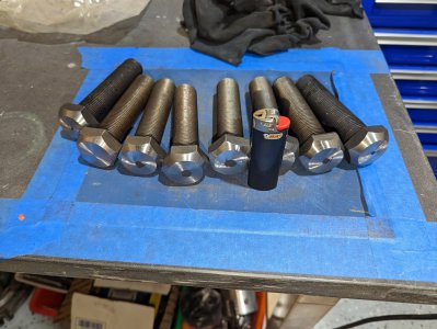
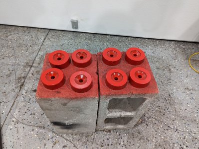
Do your 'little red feet' all have 3 contact points, rim contact or just flat on bottom?
On my LeBlond, I turned the bolts to round to fit the VEE in the feet, as the feet have 3 contact points and conform to the floor. The rounding makes intimate contact with the vee producing self-aligning support....
On my LeBlond, I turned the bolts to round to fit the VEE in the feet, as the feet have 3 contact points and conform to the floor. The rounding makes intimate contact with the vee producing self-aligning support....
- Joined
- Apr 23, 2018
- Messages
- 6,830
Do your 'little red feet' all have 3 contact points, rim contact or just flat on bottom?
On my LeBlond, I turned the bolts to round to fit the VEE in the feet, as the feet have 3 contact points and conform to the floor. The rounding makes intimate contact with the vee producing self-aligning support....
Alas, no, they are plain flat on the bottom. I don't think it's going anywhere, though. It doesn't do the jitterbug like a shaper does.
- Joined
- Apr 23, 2018
- Messages
- 6,830
- Joined
- Nov 22, 2022
- Messages
- 524
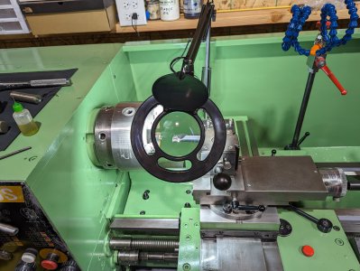
That Lathe Looks Awesome Dude!

