Redlineman's Logan 200 Rescue

Thanks TOAG;

I sort of had the gist of the lathe broaching, but I always like to SEE things done.

Thanks to the good folks here for their willingness to help without resorting to condescension and ridicule. Apparently sheaves are too rudimentary a topic for some forums to manage. :nuts:
 
Can't believe there is not one on Epay! I guess they just leave them on the motors then they are pulling them apart.

There is a guy on CL from Lake Villa IL, that usually has some stuff listed. Has both 10 & 11" parts.
Here is a link:
http://chicago.craigslist.org/nwc/tls/4285778039.html
Looks like he only takes replies by phone ... but it might be worth a shot.
 
-

Exceptionally minor forward progress;

LoganMotorPulleys.jpg

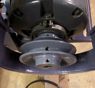
No luck on a correct used early pulley, only a new one from Logan. Good reminder from someone on Surplus Center. Didn't think of them. Not overly keen that they are from Chiner, but that's the way things are these days. Nicely enough made, at least. Pulleys are not the exact size "required," but pretty close. Two of them + a belt + shipping; all in for $30. With the addition of a new set screw hole**, it should work just fine. Worst case, I might have to mill down the shoulder on the outer pulley a tad, but a straight edge says it clears as of now.


** How much patience does it take to make a set screw hole? Quite a lot, in this case. How much FEEL? Quite a lot. Cue that twangy guitar from the Cialis commercial. "This is the age of knowing how to get things done" the man says. Indeed. How many taps and screws have you busted, learning how to feel The Edge? Chart says #7 drill for a 1/4-20 tap thread. Tap says "You really gonna twist me this hard?" (Cue the guitar again) Guy who knows how to get things done says, "Nah... I'm taking you out farther, son." Step by step by step all the way to a #1 'till the tap stops jawing and starts working. Counter bore the top of the hole a 1/64th over even, because the tap is too short. No snapped tap, no tears, no worries, done. That was a lot for a simple hole. Play that guitar. Where's that babe, and those bath tubs?

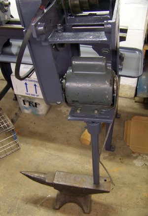
LoganPrimaryDriveWorkStand.jpg

Like my work stand? :tiphat:
 
hahahaha!
i have oversized a few holes to tap 1/4-20's. I look at the material being tapped, if its AL or brass, i go with a 7, if its steel or harder, i go a smidge bigger and save the tap. there isnt anything more frustrating than a broken tap... save maybe a broken "easy-out" in a broken bolt.
back story time!
I was fixing a test stand once in a few careers ago, and it had a broken bolt in it. I had never worked with the engineer before and he thought i was a bit green. the lead engineer saw the broken boldt and said 'there are some 'easy-outs' in that drawer'. i was milling something on the bridgeport that was theere and without looking up i said "there is nothing easy about easy-outs". he replied "oh, you've used them before". that day on he asked for me to do his test set-ups and really treated me like a seasoned pro... often asking my opinion (i know i was shocked too).

you lathe is really looking nice, love the work stand. let me know if you want to trade it for a couple CMU blocks :rofl:!
 
WOW!

Lot's of fuss over a latch! I had figured what it was supposed to be, knew that they were not shown in the prints, that originals were not common at all, nor available new. I just wanted to see one for real. I had thought of spring steel like the original, a toggle latch, and I like the magnet idea, except for the empty holes left behind. I'll decide on something by and by.

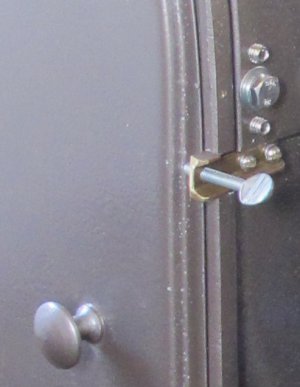
I missed this latch discussion a couple of weeks ago but I figure I might as well show mine. The original on mine was missing and had been replaced with a bent nail. I scrounged around the shop and found this little scrap of brass channel, a wing bolt and two screws. It was originally intended to be a temporary fix but it has worked so well I don't think I will be changing it anytime soon.

KustomDoorLatch.jpg
 
Hmmm...

That's pretty resourceful. MacGyver would approve. Mine had a piece of wire. Gives me a further idea on that theme. What about replacing the wing bolt with a spring pin? not that I want to over think it, necessarily. if I remember next time I order from McMaster Carr or similar, I might snag something similar. Might make something along those lines. Whatever. Thanks for posting!
 
Last edited by a moderator:
It's the Little Things that Drive You Nuts!

Hey;

I wrote recently about taking lots of pictures before you begin a project like this so that getting it back together will be easier. So easy in this digital age. Take lots of pics I said. You know... my own advice really helped again, if by accident!

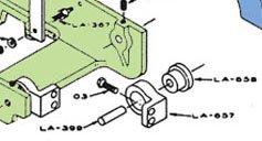
Here's a little trifle that has taken some valuable moments out of my life this afternoon. How do the little brackets go that mount the drive box to the back of the headstock? No big deal. Working on the sage advice of those who steered you into buying the parts manual, you find the requisite page, peruse the diagram, and get the info you need. This is how part LA-657 sits, and on they go. This is an excerpt of my colored version of the Logan isometric diagram that is in the parts manual, clearly showing how they sit in relation to the mount holes in the drive box.
LoganDriveBoxMountLate.jpg

So on they go and... what? This can't be right... A quick check with a ruler easily confirms this snap diagnosis. Huh? Said documentary photos loom large at these moments, so back into the computer files to see what we can learn. Not a one of them was taken to document this little detail. After all.. who knew? Ah.... wait... there's one that accidentally shows the direction they go! The diagram is WRONG! :angry:

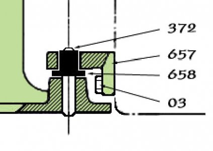
Out of curiosity, I take a look at another piece of documentation that "far too many" idle hours floating about the internet have produced. An early sectional view of the same assembly that predates the isometric versions that Logan did later. These early schematics are decried as hard to decipher relative to the exploded versions that came later, but they do prove their worth. Yet more idle moments have seen me coloring and cleaning them to improve the contrast.
LoganDriveBoxMountEarly.jpg

What gives? This clearly shows the mounts being reversed from the other diagram. Was there some sort of running change in the parts spec, or did Logan blow it when drawing up the later diagrams? Hard to say, but the combination of this early schematic and my photos set me on the right course, at last!

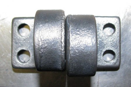
Sort of... If that was a puzzle, this is a conundrum. How do they go now that I know how they go? These are supposed to be the same part, but these... aint. Should I have freekin mark matched these damn things before I took them off. Again... who knew?
LoganDrvieboxBrkts1.jpg

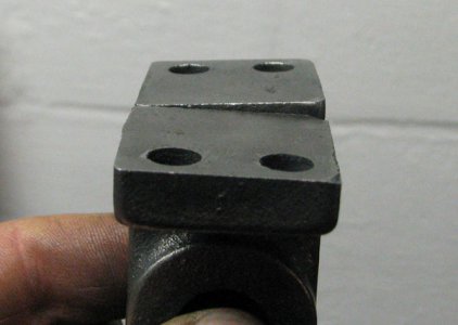
Here they are on a surface plate, lined up on their perimeter. One can only imagine the speed at which these lathes were being thrown together back in the war years. Hey... whaddaya want for a dollar-two-ninety-eight? Well, maybe three-two-ninety-eight, but... They clearly had a part tolerance here that you could drive a truck through. Do these angle up or down? The guy jigging these up on the grinder clearly had his good and bad moments!
LoganDrvieboxBrkts2.jpg

In the end, I don't imagine it is very critical and can be worked around by the now-seen-as-wisely generous tolerance on the mounting holes. It'll work out just fine, but it sure throws you for a loop, if only momentarily.
 
I'm guessing Logan was counting on those rubber bushings to make up for misalignment.

I have steel shoulder plugs instead of the rubber bushings, which can't do much for vibration control. Time to start looking for soft plastic or some other suitable replacement.
 
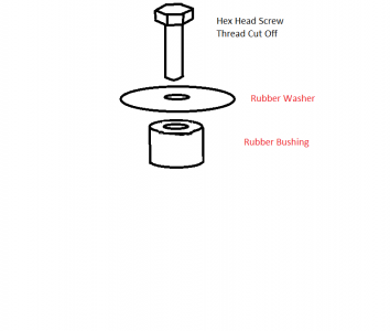
When i was doing mine my rubber bushings #658 were toast. I couldn't find a correct size bushing with a flange on it like the original. I ended up using a non-flanged bushing, a rubber washer and replaced the straight pin with a new pin with a head on it to hold it in place. The "new pin" is really just a partially threaded hex head machine screw with the threads cut off. The rubber washer and bushing came from McMaster Carr but unfortunately can't find the old order with the part numbers. Below is a crude paint drawing. I guess I should really have drawn the rubber washer on the bottom rather than the middle to show the order of assembly correctly.

RubberBushing.png
 
Hey;

Logan does sell something what appears to be a direct replacement for LA-658. One of mine is OK, but the other broke apart. Sometimes it's just easier to go this way, regardless of price. Save the brain cells for more important tasks.

http://store.lathe.com/nsearch.html...chsubmit=Search&vwcatalog=yhst-92110205831552

I managed to lose the tiny Woodruff key for the tailstock hand wheel. Now I get to buy a bag of 50 from McMaster Carr to get the one I need. :dunno:
Anybody happen to have one they can measure? The slot measures closest to 3/32 x 3/8, as near as I can tell...
 
Back
Top