SB Heavy 10 (10L) Rebuild - Model CL8187ZN

opsoff1

H-M Supporter - Gold Member
H-M Supporter Gold Member
Joined
May 2, 2015
Messages
104
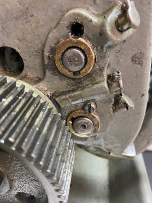
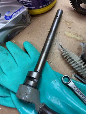
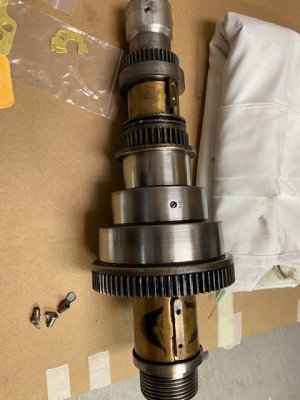
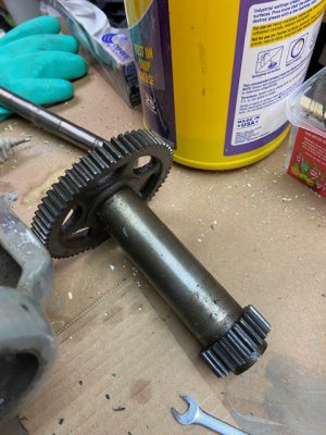
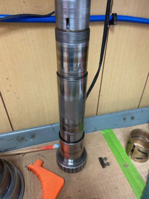
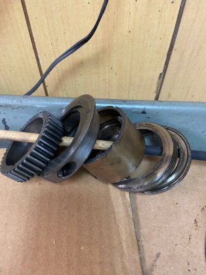
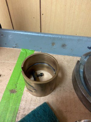
Last March I started on a rebuild project for my Heavy 10 that was initially a search for an annoying chirp that came from the headstock. This whole effort was the very definition of "mission creep". The "chirp" was finally traced to the corner of the leather belt joint that had become burnished and would make this annoying sound every time it came around the spindle pulley. Skipping ahead - It was time to replace the belt - I wanted a glued synthetic version - so I figured that this would be a good time to pull the spindle and do a little housekeeping; new oilers, check the bearing clearance etc.
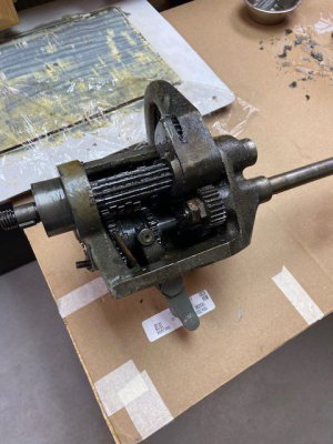
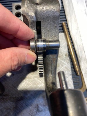
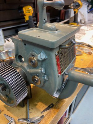
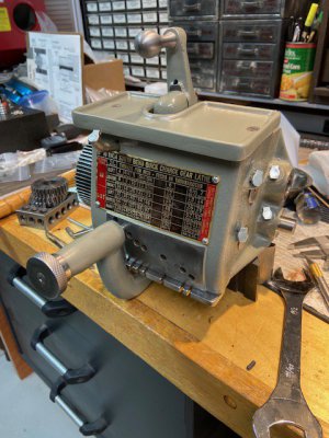
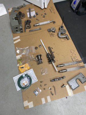
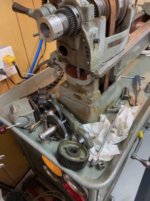
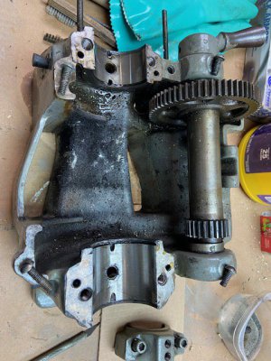
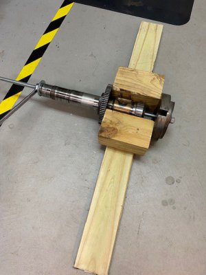
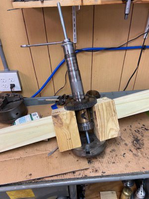
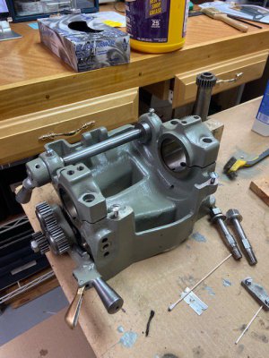
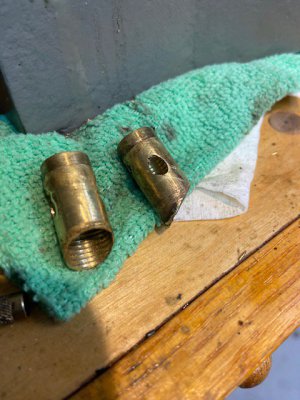
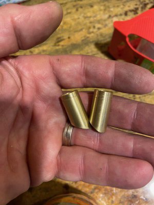
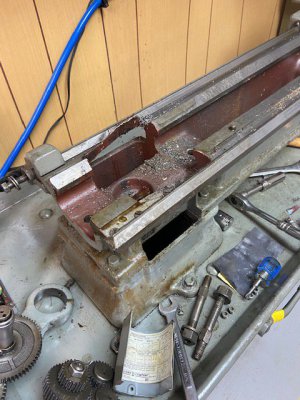
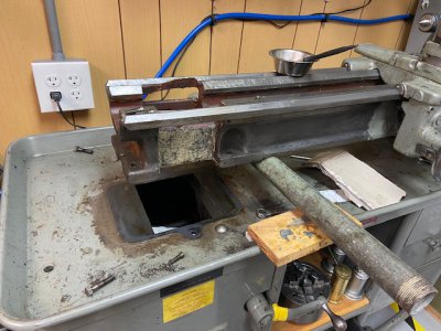
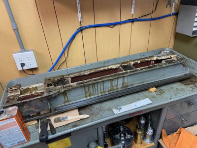
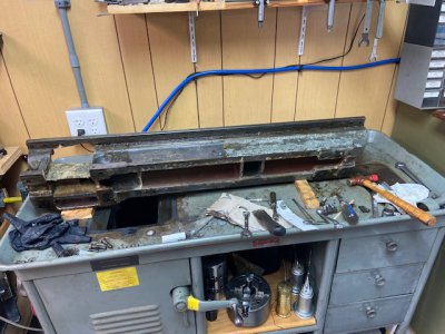
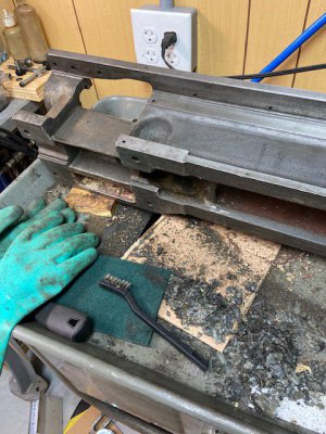
To say one thing led to another is a gross understatement... A week later, the entire lathe was completely disassembled on my shop floor. Everything.
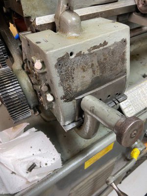
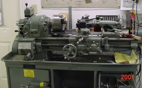
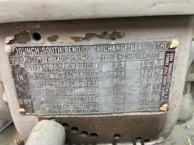
My courtship with this machine started back in 1991 when I bought it from a relatively local used tool seller that advertised in a rag known as the Want Advertiser - he was a "fixer upper" kind of guy who had clearly cleaned it up and put a nice coat of Rustoleum on it and added a repro thread chart and little labels for all the controls. He threw in a 3 & 4 jaw chuck, face plate, dogs, drill chuck, live center etc. I think I paid $600 - may $800 for it then. I was happy.
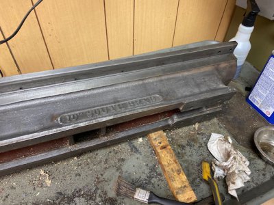
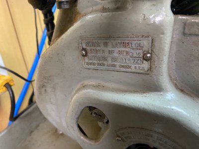
It was a 1945 era 10L, Tool Room model w/ a 3-1/2' bed with bronze bearings in the headstock. It was ordered in Aug 1945 and shipped to Westinghouse in Springfield MA who were building torpedoes for the Navy at the time. It ran decent and I learned to overcome/work around it's shortcomings. It had it's quirks, but they weren't anything that were showstoppers. Over the years, my set up times were becoming longer and longer as I had to account for wear and at the same time, I wanted more & repeatable precision. A rebuild/restoration was always in the back of my mind that I would do it at some point - that time had now come.
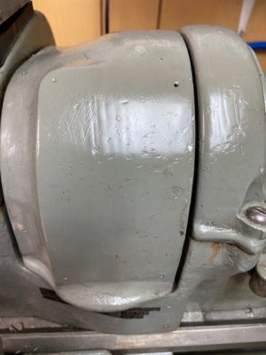
The earliest picture I have of it is in an old shop from 2001 - I had had it 10 yrs by then and was already fully attached LOL A few other pics show the state of the machine in smaller detail.
 

Attachments

  • lathe - 2001.jpg
    lathe - 2001.jpg
    110.7 KB · Views: 28
  • IMG_0174.jpg
    IMG_0174.jpg
    122.7 KB · Views: 25
  • IMG_0175.jpg
    IMG_0175.jpg
    52 KB · Views: 23
  • IMG_0177.jpg
    IMG_0177.jpg
    71.6 KB · Views: 21
  • IMG_0178.jpg
    IMG_0178.jpg
    68 KB · Views: 25
Last edited:
One of the first areas that I got into was the gearbox. Once it was disassembled and cleaned - I could really see the areas I needed to address and there were a few. The bronze shaft bearings were very worn and needed replacing. The single tumbler idler gear was also really bad. The pinion gear was also in really tough shape. This set up to what became the norm throughout the rebuild - I could source a NOS item and another part right next to it was unobtanium. Such was the case here. I ended up having the idler gear made (27T 14-1/2 PA) and found a NOS pinion gear (thanks to SB Ted). I ended up making new bronze bearings after cleaning up the shaft journals. Virtually all the internal gears were in great shape. I found another single tumbler gearbox locally that was FILTHY - but from a wear perspective, it was a gold mine. I was able to cannibalize for what I needed. Some of the pics below illustrate what I found.
 

Attachments

  • IMG_0222.jpg
    IMG_0222.jpg
    78.2 KB · Views: 13
  • IMG_0221.jpg
    IMG_0221.jpg
    85.1 KB · Views: 13
  • IMG_0232.jpg
    IMG_0232.jpg
    72.4 KB · Views: 14
One of the most unexpected results of this - I knew it somewhere in the back of my mind, was the inevitable learning curve - to fully understand every aspect of the machine - it became a joy to work on it. Understanding every bit of it and how it worked. They really are VERY simple and ingenious in the design. A good example of this is the various revisions of parts that evolved throughout its manufacturing. The single tumbler gearbox used at least two different versions of the tumbler arm/idler gear that are unique.
The early version is shown by the second picture from the right - and uses a idler gear mounted on a shaft that is only supported on one side. The next version shows the newer style with the gear sandwiched between the arm and it also rides on a roller bearing - the gears themselves do not interchange.
Note that the idler gear shown on the far left is the severely worn out one - this was replaced with a newly made piece along with a new roller bearing. (the early version of the gearbox is QCG-100, the later w/ the bearing is QCG-101)
 

Attachments

  • IMG_0307.jpg
    IMG_0307.jpg
    67.1 KB · Views: 11
  • IMG_0300.jpg
    IMG_0300.jpg
    90 KB · Views: 11
  • IMG_0299.jpg
    IMG_0299.jpg
    88.9 KB · Views: 11
  • IMG_0298.jpg
    IMG_0298.jpg
    91.5 KB · Views: 11
Last edited:
I used a LOT of Purple Power and Zep Purple to clean, degrease, strip the parts through out the rebuild. (wear rubber gloves! LOL)
In what became standard practice throughout - once I was down to bare metal, then I could start measuring / gauging / checking parts for damage or wear and the search would begin. I put forth a lot of effort to clean completely - every oil passage / feed / wick area etc - it was amazing how much **** came out of all these areas.
Pictured below are the parts laid out - and the reassembled gearbox. New felt throughout, new Gits oilers, new bearings, new idler gear, NOS pinion gear, restored brass thread chart. Note that the Primary Drive gear has a chipped tooth - this was also replaced with a NOS item. I added an extended Gits style oil tube to the front of the gearbox - in my opinion, this is probably the Achilles heel of the gearbox attributing to a LOT of wear on the idler gear and the pinion gear. That hole normally has a brass plug that is supposed to be removed and oil is fed into the hole which lines up with a small reservoir/feed hole for the two gears - it will only get oiled if the tumbler arm is placed in the first slot. Over time as shops turn over equipment, young users come in - that plug gets lost - the hole gets plugged and adding oil there is forgotten about.
All data plates on the entire machine were restored and new drive screws used to reattach them.
 

Attachments

  • 70916766203__1939E842-0F98-4AE3-B9C2-8AA855D1F35D.jpg
    70916766203__1939E842-0F98-4AE3-B9C2-8AA855D1F35D.jpg
    78.7 KB · Views: 20
  • 70916764029__B3535562-C0AC-4103-85B3-24D52CAA50A4.jpg
    70916764029__B3535562-C0AC-4103-85B3-24D52CAA50A4.jpg
    78.4 KB · Views: 20
  • 70916761372__C0E5E07F-6FF7-4078-92B4-A0179ABDBC63.jpg
    70916761372__C0E5E07F-6FF7-4078-92B4-A0179ABDBC63.jpg
    84.3 KB · Views: 21
  • 70506798421__68461DF0-8F67-4781-A1EC-086321BF60F0.jpg
    70506798421__68461DF0-8F67-4781-A1EC-086321BF60F0.jpg
    73.1 KB · Views: 20
Last edited:
After the gearbox - I went after the headstock & the gear train - not as bad as I expected, but it was dirty and it clearly had some struggles getting oil to flow through the correct way. I did experience the spindle shedding oil from behind the chuck. It turns out that both oil vents holes had been painted over - in my semi ignorant state - I just kept adding oil every time I used it - so I probably saved it a little from just over lubing it. The spindle bearing journals were in fantastic condition - the bearings...not quite. I was able to source a set of NOS bronze bearings with expanders and screws. At some point in the machines life, the bearing caps were improperly removed - and the expanders were pried up out of the bearings. To add insult to injury, they were reinstalled wrong as well - imprinting the expander into the top of the bearing - the fact that it ran as well - relatively speaking, as it did is a testament to the robust design. The oilers were (ahem..cough..cough) serviceable. Needless to say - everything was replaced.
Also - note in the last pic: the back gear adjustment screw (dog point) is broken in two. That was replaced with a new mfr'r unit.
Also note: the oil wick brass tubes are pushed down flat with the journal surface.
 

Attachments

  • IMG_0231.jpg
    IMG_0231.jpg
    91 KB · Views: 20
  • IMG_0423.jpg
    IMG_0423.jpg
    95.9 KB · Views: 21
  • IMG_0425.jpg
    IMG_0425.jpg
    85.8 KB · Views: 20
  • IMG_0427.jpg
    IMG_0427.jpg
    93.5 KB · Views: 20
Last edited:
I'm wondering how much of your lathe is really original. The tailstock is not. I also do not believe that bronze bearings were available on any machine made during the war, but instead the spindles ran on segmented CI bearings. This makes me think that your headstock is also not original.
 
Some of the more glaring issues surfaced here. The bearing cap shims were a mix of what appeared to be OEM parts and home made items that looked like that had been cut out with the Mrs' kitchen scissors. The backgear adjustment bolt had the tip sheared off - still inside but in two pieces. Here is where I ran into a problem - my arbor press was not big enough to fit the spindle in - so some RN engineering was required.
A makeshift press was built with some 4x4's, 1/2 threaded rod, washers, nuts etc. Everything came off quite easily. A gear puller was used for the spindle (back gear) gear.
 

Attachments

  • IMG_0428.jpg
    IMG_0428.jpg
    82.5 KB · Views: 18
  • IMG_0429.jpg
    IMG_0429.jpg
    75.5 KB · Views: 16
  • IMG_0529.jpg
    IMG_0529.jpg
    63.2 KB · Views: 14
  • IMG_0528.jpg
    IMG_0528.jpg
    81.8 KB · Views: 13
  • IMG_0523.jpg
    IMG_0523.jpg
    79.7 KB · Views: 14
  • IMG_0432.jpg
    IMG_0432.jpg
    66.2 KB · Views: 14
  • IMG_0431.jpg
    IMG_0431.jpg
    82.1 KB · Views: 14
  • IMG_0530.jpg
    IMG_0530.jpg
    66.9 KB · Views: 14
  • IMG_0531.jpg
    IMG_0531.jpg
    73.7 KB · Views: 13
  • IMG_0532.jpg
    IMG_0532.jpg
    65.7 KB · Views: 17
Last edited:
I'm wondering how much of your lathe is really original. The tailstock is not. I also do not believe that bronze bearings were available on any machine made during the war, but instead the spindles ran on segmented CI bearings. This makes me think that your headstock is also not original.
I have thought about this - the HS part number matched to what was on the original invoice. That being said - I am assuming that a CI bearing unit and a bronze bearing unit would at least have different revision numbers. So....??? Honestly - I am overjoyed it has bronze in it even if it makes it a franken lathe.
You are correct re: the tailstock - that P/N or Unit number in SB speak does not match the original invoice.
 
Last edited:
NOS bearings went in as did NOS thrust bearing and washer. Brand new shims were used, new oil wicks, etc. All the bolts & oil passage plugs were refinished in black oxide. The brass tubes for the spring loaded oil wicks were removed. At some point in the machines life, the tubes were pressed down and no longer extended up into the bearing. In addition they were partially rotated so that the oil passage holes were partially blocked. I was able to thread a tap into them and pull them out. New ones were made from brass tubing - new oil passage holes were reamed once they were in place to align correctly with the passages in the headstock. While they were out - a considerable amount of time was spent cleaning the oil passages, feeds, vents & reservoirs - spotless as I wanted zero debris remaining - a lot of crud came out of these areas.
As with everything else - bare metal was primed and them painted (by brush) with a Sherwin Williams custom mix that someone posted here or another site - it is deadnuts for the SB color as I have been able to compare it to NOS parts.
 

Attachments

  • 71702741248__469A270C-6618-4385-92AF-033CD45C3A80.jpg
    71702741248__469A270C-6618-4385-92AF-033CD45C3A80.jpg
    66.1 KB · Views: 11
  • 71450234677__11E162D3-34E3-46DE-92F0-1E4E1938B2C4.jpg
    71450234677__11E162D3-34E3-46DE-92F0-1E4E1938B2C4.jpg
    87.7 KB · Views: 12
  • IMG_0688.jpg
    IMG_0688.jpg
    74.3 KB · Views: 10
  • IMG_0690.jpg
    IMG_0690.jpg
    60.4 KB · Views: 11
Last edited:
After the HS - came the apron. Prior to starting this - I focused hard on striping the bed, saddle, cross slide & TS base. These parts were dropped off with Rees Acheson for him to plane and scrape. He is an absolute gem of a man. Pleasure to work with and is just overflowing with knowledge and experience. Below are some pics of these components in prep and getting ready for the trip. I found during this process that there were 5 layers of paint on the bed - starting with a maroon primer, then SB Gray, then a gross beige, then two more coats of gray. Crazy. Striping the bed was a lot of work - the only thing worse was the bench/cabinet.
 

Attachments

  • IMG_0426.jpg
    IMG_0426.jpg
    90.8 KB · Views: 20
  • IMG_0454.jpg
    IMG_0454.jpg
    110.8 KB · Views: 18
  • IMG_0481.jpg
    IMG_0481.jpg
    140 KB · Views: 19
  • 71450239255__80561FFC-25E0-414A-A808-F3BEBB7B3C25.jpg
    71450239255__80561FFC-25E0-414A-A808-F3BEBB7B3C25.jpg
    105.6 KB · Views: 17
  • 71702738524__6CF0D3FD-A52E-4C9B-97BB-44C773DA9A88.jpg
    71702738524__6CF0D3FD-A52E-4C9B-97BB-44C773DA9A88.jpg
    102.7 KB · Views: 18
  • 71702737154__CBBDF933-DDD3-44EF-BBB6-041C16FFDC19.jpg
    71702737154__CBBDF933-DDD3-44EF-BBB6-041C16FFDC19.jpg
    120.4 KB · Views: 16
Last edited:
Back
Top