Transfering/ laying out holes for adapter plate.

If there is enough register to engage the chuck, these might work. Blind hole spotters

View attachment 438771
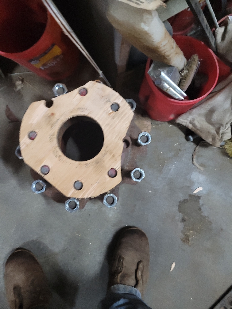
Those would work , kind if my thought of running the pointed set screws through the mounting holes into the plate after machining the index.
Still searching for a piece of scrap to even try. Scrap in this area had become slim. Scrap yards dont trade/sell back over the counter anymore,
 
I would measure the hole to hole distance first. With a digital caliper, set the inside jaws in one of the holes on a diameter and zero the caliper. Then measire the outside to outside of two holes. The reading will be the center to center distance. Do this for all three hole combinations and average the readings. The radius of the bolt circle will be .5773 x the distance between the holes. Use a compass to scribe that rafius circle onto your work. Then wothout changing the compss, walk it around the circle, scribing an intersect line with the circle. The sixth scribe should bring you back to the first point. Every other scribe intersection will be the location of a hole. Check the hole to hole distance with your caliper to verify your work.
 
This kind of stuff really intrigues me. I love it! I don't know it very well but it sure is interesting. This is one thing I regret not learning in high school, I had the opportunity to, I just never thought would need it.

Here is a Joe Pie YouTube that might help. Although between RJ and Pontiac you should get.
 
Cardboard, plywood or any other flat surface works.

Practice making the part from. Saple material until it fits, then repeat on real thing, see below.

We picked op a rotary table/index to make an adaptor plate for a BBQ project.

The hub is from a fire engine, needed to make a plate to attach post for support.

Made a test part from plywood and cut hole similar size to actual part.

Gripped by center so placement only needed to line up with one hole, drilled 8.

Very little clearance for bolts, fit was soon good that the screws need to come out to remove as any tilt binds it.


Did not need accurate placement
16857f71373435c990efa5faef58781e.jpg
ad1dbe8a72d3996a1fd6b6a578d4f022.jpg
8c0bb67915b7a986064af6a3283e91a3.jpg
9a4fe570f200ed0b52baccba20f7b160.jpg
dd1906c1a25b6630fcc6724a270374f1.jpg
521650a6a34971a1fe9e4d6c062cf4b5.jpg


Sent from my SM-G781V using Tapatalk
 
You might take a piece of drill rod that fits snugly on the holes and machine a point on them like a transfer punch, harden them and make them just long enough to barely stick through the spindle flange and mount the adaptor plate on the spindle flange and tap the 3 transfer punches just hard enouth to make a mark, which can be deepened with a center punch and do the drilling.
 
I get it for those trained and working in the art. Im a complete beginner. I will have to read up more on layout.
I dont have a rotary table, eventually I will come across one. Like I did this chuck.
do you already have a chuck for the lathe?
if you do, make a center plug for your new chuck. put a light center dimple in it using the tailstock and a centering drill.
Now you have a place to put your compass, and now it should be easier to create the layout.
You might want to do the same for your spindle hole, so you can verify center to hole and arcs..
What John (@pontiac428) showed is how we did it long, long ago, and works quite well. I still swing arcs for many layouts (especially for wood working) because that's how I learned it.
Having a little visualization failure on this , thats probably my road block is I have just never seen it done. Any and all help and tips much appreciated.
 
I would measure the hole to hole distance first. With a digital caliper, set the inside jaws in one of the holes on a diameter and zero the caliper. Then measire the outside to outside of two holes. The reading will be the center to center distance. Do this for all three hole combinations and average the readings. The radius of the bolt circle will be .5773 x the distance between the holes. Use a compass to scribe that rafius circle onto your work. Then wothout changing the compss, walk it around the circle, scribing an intersect line with the circle. The sixth scribe should bring you back to the first point. Every other scribe intersection will be the location of a hole. Check the hole to hole distance with your caliper to verify your work.
Sounds good when I read it, lol
Im going to have to get a compass the small one in my desk only spreads to 3”
 
Some years ago, I bought this little book :
It's full of exercises in this kind of stuff - A lot of fun, actually
Full disclosure, my wife has a master's in math education and taught for a number of years. She kicks my butt at math and loves geometric construction. We have a 5 foot slide rule hanging above the TV in the living room, because the 8 foot slide rule wouldn't fit (it's in the shop). So I have a full time live-in geometry consultant who can go from true zero to non-euclidian at the drop of a hat.
 
Back
Top