Volvo Amazon 1965 (Volvo 13134)

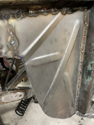
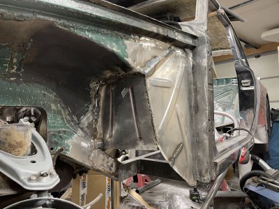
Faster than a bullet I lost track of the frame reinforcement idea and started experimenting with some sheet steel to cover this area up.
IMG_8312.JPG

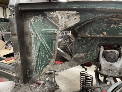
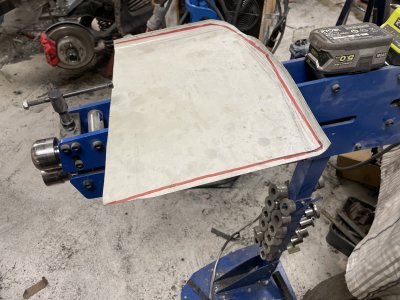
This body shaping stuff can be quite challenging, I often struggle with understanding how I even want the shape to end up but I figured I'd start with rolling the corners so I'd get a bit of a radius meeting up against the body.
I decided to not try and follow the perimeter as any turning when rolling a corner, this much and with this big of a radius, will bend the plate and be very hard to shrink straight again. Instead I did 2 mostly straight runs like this and then spent a good 2 hours with hammer, dolly, english wheel etc to try different things out.
IMG_8315.JPG

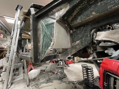
Initially I 'English wheeled' it so the bubble went into the car but this looked horrible, especially since the "side firewall" is a bit further behind than the sheet in the engine bay so the white plate ended up being both a hole and leaning backwards.
Luckily once a volume is established it can usually be punched the other way relatively easily.
I imagine it would've been way better to make a wire buck to try some shapes out without having to form an entire sheet.
I did start with a paper template but it's a difficult shape to "understand" with just paper held up mid-air.
IMG_8316.JPG

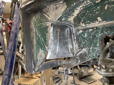
Bit more work and also spent quite some time cleaning up/grinding down welds all around this area.
Doesn't make much of a noticeable difference but every bit counts.
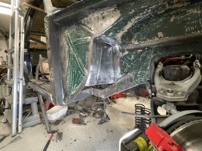
Was quite challenging getting the shapes to line up, took quite a bit of twisting and shrinking on the left side.
Due to the angle and twist in the panel the beads look real wonky but at least they make the sheet really stiff.
IMG_8320.JPG
 
looks good, but man you need to up your template game and get yourself some cardboard! Thin, single wall and double wall should cover all eventualities.
 
And make my life easier? Bah! :grin:
I've been wanting to get a mix of template material for quite a while but it's hard to find an affordable source. I have a lot of kraft paper but for things like this it's too flimsy. Really need to supplement it with cardboard like you say.

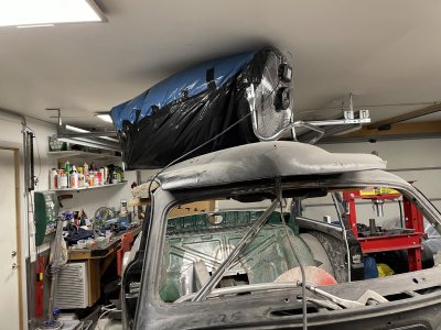
Other issues right now is the winter outside. Grinding and welding makes for horrible air quality and the garage quickly becomes foggy and full of dust. When outside temperatures are OK I have the garage wide open but that's not possible right now. Even having it open for a few minutes makes it uncomfortably cold.

So a little workaround had to be bodged together..
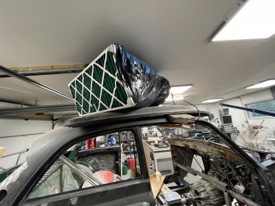
60 cm diameter and 120W fan, taped to 2 trash bags, taped to a large filter.
The fan makes sure the bags stay inflated and with such a large filter the through flow is quite impressive, you can feel a breeze all across the filter.
The somewhat long trash bags also helps dump the air a bit away from the fan to really recirculate the entire room.
It also a proper eye-sore but sure beats having a ton of particulates floating around in the air messing up my lungs since it's not always possible to wear a respirator. Should at least take care of any sanding/grinding related dust, welding smoke will still be a problem but I can work around that in other ways.
IMG_8342.JPGIMG_8341.JPG
 
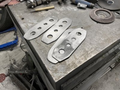
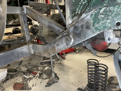
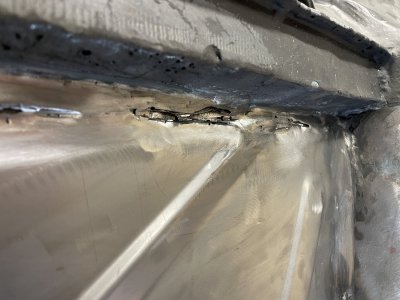
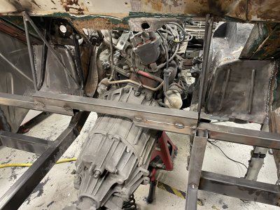
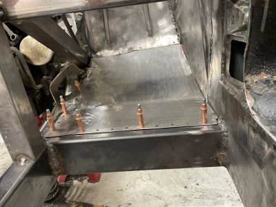
Thought a bit more about the frame joint overlaps. I'm just gonna trust the welds where I have welded the same type of tube to eachother and only reinforce where the thicker tube joins to the thinner original chassis since this is always harder to weld and a potential weakspot.

Made some parts to overlap the joints and drilled holes for throughwelding.
This was all very much shooting from the hip with little thought, downside of working on things when you're short on time.
IMG_8327.jpeg

Followed by just as rushed welding, came out so bad that I've been hesitant to keep working on it. :hate:
Uncomfortable angle, wrong settings, wrong method etc resulted in a very blotchy finish.
I think I will grind this down around the entire perimeter and reweld it properly so I know it's strong, and looks good-ish.
IMG_8328.JPG

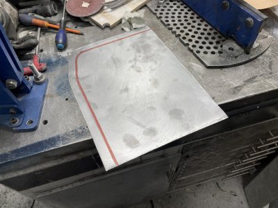
Whilst I recover from that disappointment I started experimenting with the firewall on the driver side, trying to replicate the panel I previously made but mirrored and try to improve my process of shaping it.
Started with flat sheet, following my old template.
IMG_8380.JPG

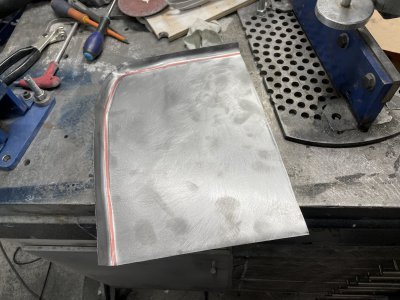
Beadrolled the entire perimeter at once this time, several passes, gradually forcing it to more and more of an angle.
Using a big radiused wheel ontop and a flat wheel on bottom, manually pushing the sheet against the radius whilst the flat piece provides the grip to move the sheet through.
Eventually the "corner" becomes a limiting factor as there's just too much material and it keeps "reseting" the sheet around it.
IMG_8381.JPG

Played around with my shrinker/stretcher which helps get the corner up but very hard to work around this area since the corner is so tight, it's near impossible to get it into the jaws and only gets worse the more you tip it up.
IMG_8382.jpeg

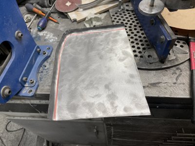
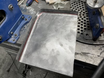
More alternating passes between beadrolling, hammering, shrinking etc.
Pay attention to the red line and you can see how it's "moved up" the edge as I'm bending the material up more and more.
Again more need to shrink the top left part etc.
Now the next difficult part is starting to crown the flat area and 'skewing' it diagonally to match up to the outside panel of the car.
To be continued.
IMG_8383.jpeg
 
Somewhat related to the car project.
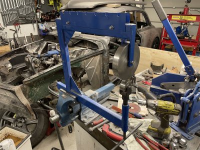
I have a tool/toy of an English wheel, the square tubing is like 40x20x2mm, very flimsy.
With enough pressure to shape steel, the frame has opened up by 1-2cm.
It works but makes it very difficult to control the pressure.
I have enough hours on it that I feel like it's a good-ish tool that gets let down by the rubbery frame.
IMG_8386.JPG

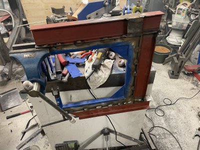
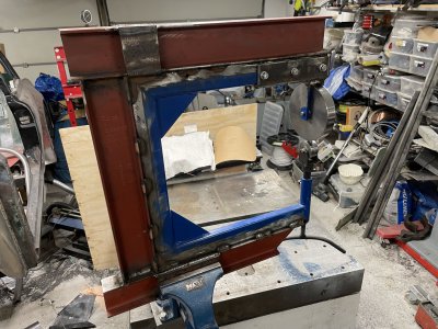
So I looked into my pile of scraps and found some I-beam.
Rough calculations shows this should be 7x as stiff as the tubing, and welded together it should be much stiffer than that 7x alone.
Should make A LOT of difference when it comes to feel and I'm also low key hoping I can make it dual purpose and make an attachment for my pneumatic hammer and an anvil.
That'd let me experiment with some different planishing techniques that would've come in handy several times already.
To be continued..
IMG_8387.JPG

Sidenote: I REALLY need to work on my stitchwelds. I always think I can judge distances by eye and it ends up looking like absolute chaos.
 
Managed to get the last details sorted on this.
Could've saved some time doing it differently but I figured the extra time and complexity would be well worth it.
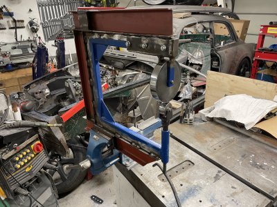
What I ended up doing was cutting the entire wheel assembly off and making it into a separate attachment.
The fit is very tight(might even need to sand the beam a bit to loosen it) and then held in place by 3x M8 screws.
IMG_8400.JPGIMG_8401.JPG

I'm usually fairly stoic but WOW this made a world of difference.
Before you could tension the wheels against each other, quite a lot, and still push steel sheet into it.
Now if you even put the wheels against eachother, it's extremely difficult to push a steel sheet into it.
Might not sound like an obvious advantage but this makes it much easier to both set and 'feel' how much pressure you're applying.

Only reasonable way to crown a plate before was to use a sharp wheel(full small radius) and apply quite a lot of tension(easily 2-3 revolutions after making contact). Not only would this leave obvious marks in the sheet but also made it very hard to control how much shape was created.
Now I could use the flattest wheel I have(can barely tell it's radiused), apply maybe 1/4 of a revolution after making contact and then start rolling.
Not only does this make it much more precise and allows you to do a smooth and low crown, the flatter wheel makes it much harder both to shape too much and make tracks/dents from the wheels. Overall I'm so happy I spent the time on this. :grin:
IMG_8402.JPG

So what's the purpose of making the frame itself modular?
IMG_8405.JPG

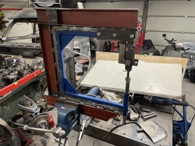
Well, now I can use the same frame for my pneumatic hammer, and use it as a planishing hammer.
I need to make a mount for the hammer, polish the top anvil, shape and polish the bottom die and also make a mount for it so I can easily replace the bottom dies.
The height adjustment from the 'wheel setup' stays so die height can easily be adjusted and then locked.
IMG_8404.JPG
 
very neat modification! That's why the commercial frames are so much stouter/ heavier. I've seen some of the commercial shrinker/ stretchers and they are HEAVY
 
Thanks! Yeah I have a "real"-ish shrinker/stretcher and it's probably as heavy as this english wheel is now despite being a lot smaller. :grin:

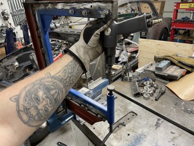
Quick and dirty mount for the airhammer to try planishing out.
Going to change how it attaches and also optimize it a bit, but that's for later.
IMG_8431.JPG

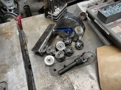
Decided to make it easy for myself and bought a few cheap extra hammers and just ground them down and polished. Alternative would've been casehardening what I have at home, which is a lengthy and annoying process.
Not super economical having such long anvils compared to how the commercial units do it but works quite well.
The more rounded ones took quite a while to make since the steel is so tough, the radius's are just by eye.
IMG_8422.JPGIMG_8423.JPG

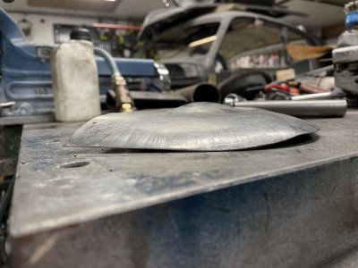
Played around with the test piece from the previous post, first with the flatter dies and smoothing it out, later with the roundest die to make a bubble on top of the plate. I think it's called making a blister or something like that.
Not super impressed with this setup, the hammer feels weak and takes a bit too long to shape stuff. After looking into this further I think the problem is my air setup and not the hammer. Gonna try hooking it up with a shorter hose directly to my compressor and compare how fast it forms.
Will give that a try some other day, now I feel like getting back on to the car. :grin:
IMG_8426.JPG

So, continuing the piece I started in post 94... I need to clean this up to start fitting it.
IMG_8435.JPG

Surprisingly good welds overall, a few places I will need to use the cutting wheel to get some depth and then reweld.
Grinding welds is probably the worst part of building things, the amount of dust afterwards is just bleugh.
IMG_8438.JPEG

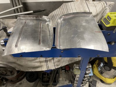
So this piece was mostly flat in post 94, afterwards I've stretched it a lot in the middle and along the right/bottom perimeter.
This makes it want to curve backwards, kinda bending diagonally if that makes sense?
Of course a lot more work has gone into it to make it fit but it's a lot of trial&error as I go along.
IMG_8440.JPG

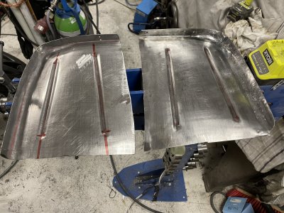
I usually don't pre-stretch before I beadroll but tried it this time. Might've helped crisp up the lines a little bit but hard to tell.
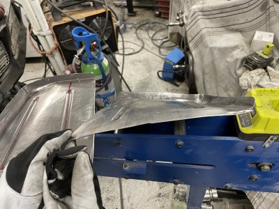
Second picture shows a bit better how 'bent backwards' these pieces are which makes the bead look really wonky on the car. :grin:
IMG_8441.JPGIMG_8443.JPG
 
Attacked the driver side weld seam I ground down last post. Were a few suspicious spot that I cut into, revealing porous welds and garbage.
A mix of brakecleaner, wire brushes and propane torch got it clean enough so I could weld it together properly and then grind that down yet again.
IMG_8466.JPG

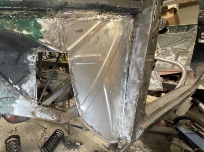
Then decided to attach the sheet parts I finished last post.
The shape was about 80% correct, the last 20% I hammered into shape as I went around the perimeter tacking things in place.
Just tacks for now, were a few places I had to bridge quite a bit but still happy with the outcome so far.
IMG_8469.JPG

Ground down the welds a bit on the other side to see how it'd come out. Still need to do quite some welding but this should be structural enough.
IMG_8467.JPG

I think next step will be either the floor connecting to the pieces I just attached or joining together the firewall again.
I don't know where my steering column is going to be so that makes me feel a bit iffy about the firewall, but I'm sure I can just weld a piece in later where it can poke through.
IMG_8472.JPG
 
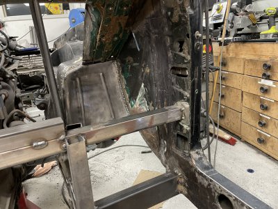
Decided to get started on the passenger foot well or whatever it might be called.
Needed to clean the right sheet metal which was a horrible task. I'm not sure what the paint is but it's extremely resilient to both chemicals and abrasives..
IMG_8474.JPG

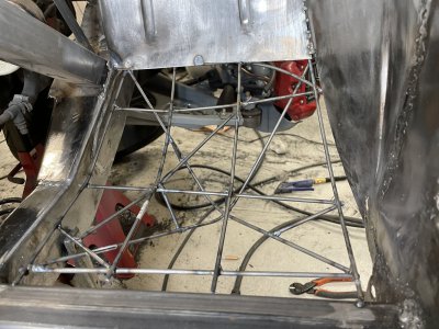
Since there's quite a lot of shapes that need to meet up at once, I tried making a wire buck.
This was probably the most fun part of the whole ordeal. :grin:
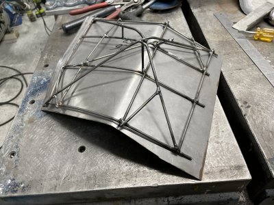
Added quite some reinforcement to the backside to make sure it keeps it's shape as I remove it from the car.
IMG_8482.JPG

Starting with a scrap piece and just bent it to the rough shape. It's not even close to touching in a lot of areas hence also needs shaping/stretching.
I had a similar issue on this as I had on the previous pieces I made. As I stretch the left perimeter to match the buck, the top corner bends away from the buck and when I fix that the middle of the perimeter is no longer touching.
Chased my tail for quite a bit before I figured out how to get around it by trying to bend/twist half the panel.
IMG_8488.JPG

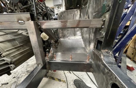
Mostly fitting well by now but had to weld in a strip on the left since the scrap piece was too small.
I always thought those clecos were a bit of a gimmick but they're honestly so nice to work with when you get the hang of it.
IMG_8492.JPG

Fully welded the strip and blended it back down, kept it's shape surprisingly well and only needed a little convincing to fit back in place.
This is basically ready to be welded into the car but I'm going to first use this to make a mirror of it, for the drivers side.
Once I have both pieces I will try to press some shapes into them, just like the upper piece.
IMG_8494.JPG

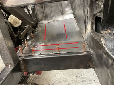
I'm considering something like this. Same vertical lines in the angled section, to align with the top plate.
Then change it up a bit on the flat section and make the lines horizontal instead. I think it will look weird/dumb with two short lines in such a wide and short section.
IMG_8494 - Copy.JPG
 
Back
Top