Needing more than a spark test?

My first attempts at dealing with the lead were interesting. A far eastern copy of an xacto knife is almost, but not quite capable of cutting 1/16" lead. I had to resort to tin snips. I cut out a somewhat square piece almost 3" x 3". I traced out the center hole. Since my cutting did not quite go as expected, I decided to make a punch and die out of steel to cut out the center hole. I used a piece of 12L14 steel 3/4" diameter for the punch and bored a hole in a 2" disk of 1018 steel. My idea is to use the punch and die to cut out the center, using an arbor press. The gap between the punch and die are currently at about 0.0005". Was pretty happy to hit that. I'll try cutting around the edges to get it roughly circular. Might sandwich the lead between some big washers and turn the edge circular. At 1/16" thick, this lead is a bit stiffer than I expected. Tin snips work fine to cut the lead. My plastic die idea might not work. An aluminum or steel die might.

Think I made the steel die OD too small. Going to be tough to align on the arbor press. Might make a steel plate with a recess in it to locate the die and clamp the plate to the press. If I turn the top of the punch to 12mm, it will fit in the ram. Then I lower the ram, line up the plate and clamp it while the ram is down. Raise the ram, insert lead, then punch out the center. That's the plan... Got to work on it tomorrow.
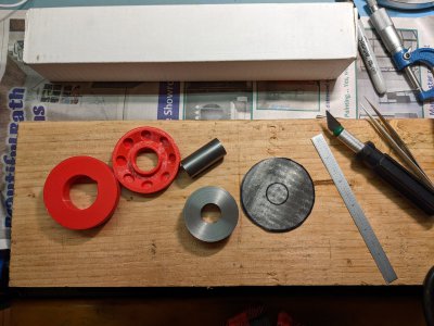
PXL_20230127_222906723.jpg
Once the hole is punched, I will make a sandwich of a steel plate, the left red piece, the lead washer, and the right red piece. Then I will put the assembly on the arbor press and see what gives under pressure. I'm hoping it is the lead!
 
@WobblyHand
Hi Bruce
What if you just stick the lead down onto the die with superglue, or something. Maybe even between two die discs. Then drill and bore it?
I will admit that I am going for the "heavy solid" approach. Something sort of "legacy Soviet" :)
 
@WobblyHand
Hi Bruce
What if you just stick the lead down onto the die with superglue, or something. Maybe even between two die discs. Then drill and bore it?
I will admit that I am going for the "heavy solid" approach. Something sort of "legacy Soviet" :)
Guess it is a matter off what I can easily make with whatever is in my shop. I'll poke around and see if an idea comes to me.

Well heavy/solid is plan B. I figured i could have machined a mold by now and cast the basic shape. My piece in plastic would weigh 210gms if lead.

How to make the pockets? I don't have a warm fuzzy feeling about that. Might have to make an aluminum set of soft jaws to hold the lead. They'd probably look a lot like the mold...
At this stage, I am easy going about the pockets. I don't even think one needs to cast any more than a cylinder puck. I am looking around for a suitable metal lid of some sort. The ex-tuna can won't do. It's too big diameter, and it's got "rippled" sides.

Also, I think turning it should be done with support in mind. Drill out the middle, and put it on a steel rod, between two discs, screwed together somehow, or maybe a couple of wood screws going through into the lead, so as be able to grip hard with the chuck on the disc, and know the lead in the middle will be forced to turn with it.

To add some pockets for the sources, I know I could go at it by tilting the head of my mill, but right now, it is being packed on it's pallet to be moved from garage to shop. The lathe does not have to move yet, but I have a clutter problem. I think, with a little care, one could gently mark out six or eight aiming points, and (carefully) drill out the pockets just using a hand drill. The tendency to "grab" and go in deep gave me thoughts. I have a loose old Jacob's drill chuck, and I think just turning it carefully by hand might work.

I am re-working the CAD bits right now, while listening to instrumental blues in my new Christmas present studio-type headphones. :)
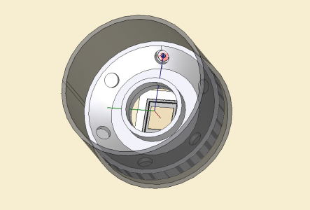
The parts are all in the wrong place relative to each other, and the source is trying to occupy the same space as the shield.
The sketch for the revolution body contains lots of construction mode lines for the photon path geometry.
I will post it here, or put it someplace you can download it.

XRF-Front-WIP.png
 
Last edited:
I made a punch setup that is meant to be installed on my mill. The die is held in my vise and the punch is installed in a collet. To align the punch to the die I use a DTI mounted in a collet and null it out as I turn the DTI.

It actually doesn't take much force to punch a hole in 1/16" thick lead.

I actually made a 2-step punch and two separate holes in my die plate so I can punch out lead rings for my focusing ring. That didn't work out too well though, I still had to add another piece of lead plate with a hole in it to cut down on the stray x-rays getting to the detector.
 
Well I'm really puzzled by something I discovered today. As I showed earlier, I'm getting distinct peaks when entering peak-voltage values into my MCA so I was expecting to get even better results when I switched back to using pulse area. NOT SO! I'm getting a peak alright, but its appearance doesn't change much between steel and aluminum samples! I am mighty puzzled by this. It's such a startling difference that I have to conclude that either: 1.... My pulse-integration code is screwed up somehow; or 2.... There's a fundamental reason why pulse area is apparently constant regardless of what element is generating the pulses. If #2....wow..,,

This doesn't mean that there isn't any way to improve things. I'm thinking about going with a higher-order polynomial fit that can be used over a larger number of points around the pulse peak. That should still improve the effective SNR but it will complicate the procedure used to find the maximum point on the curve. The most general approach will be to use Newton's method in an iterative fashion so it will be slower than the closed solution for my second-order polynomial fit. It's relatively simple to calculate the coefficients of the derivative of a polynomial so calculating x - p(x)/p'(x) can go pretty quickly. I'm already doing a quick peak-find by just looking for the maximum pulse value so by using that for my initial guess the iteration should converge to the correct maximum (a potential issue for finding zeroes of higher-order polynomials).

I found an Arduino library for fitting polynomials to data (up to a 20th-order polynomial!) so a solution for that problem is already in hand. That was going to be the heavy lift so I should be able to get something going pretty quickly....so he sez in complete ignorance! As shown by this unexpected result.....
 
Well I'm really puzzled by something I discovered today. As I showed earlier, I'm getting distinct peaks when entering peak-voltage values into my MCA so I was expecting to get even better results when I switched back to using pulse area. NOT SO! I'm getting a peak alright, but its appearance doesn't change much between steel and aluminum samples! I am mighty puzzled by this. It's such a startling difference that I have to conclude that either: 1.... My pulse-integration code is screwed up somehow; or 2.... There's a fundamental reason why pulse area is apparently constant regardless of what element is generating the pulses. If #2....wow..,,
Your pulse integration code is unlikely to be messed up. Way back, you showed it would work.
The pulse made by the Pocket Geiger was only to be detected and counted. I suspect the designers back then did not care much about preserving integrated area energy information. The most they wanted was to be able to dump a big, out of character, microphonic noise pulse with their (NS) signal
This doesn't mean that there isn't any way to improve things. I'm thinking about going with a higher-order polynomial fit that can be used over a larger number of points around the pulse peak. That should still improve the effective SNR but it will complicate the procedure used to find the maximum point on the curve. The most general approach will be to use Newton's method in an iterative fashion so it will be slower than the closed solution for my second-order polynomial fit. It's relatively simple to calculate the coefficients of the derivative of a polynomial so calculating x - p(x)/p'(x) can go pretty quickly. I'm already doing a quick peak-find by just looking for the maximum pulse value so by using that for my initial guess the iteration should converge to the correct maximum (a potential issue for finding zeroes of higher-order polynomials).

I found an Arduino library for fitting polynomials to data (up to a 20th-order polynomial!) so a solution for that problem is already in hand. That was going to be the heavy lift so I should be able to get something going pretty quickly....so he sez in complete ignorance! As shown by this unexpected result.....
Last I used high order polynomials was to fit microwave communications shaped high efficiency dish antennas. Even a 6.2m dish needed to fit to within 0.25mm. I never needed a polynomial beyond 8th order. Things get tricky when getting a fit depends on the subtraction between very large quantities, pumped up by high order powers.

I am more thinking that I should return to the simulations, and check the integration area of the start pulse for a range of amplitudes. Also, get the corresponding integrations for the pulses at the end of the chain. If they do not track linear, only differing by gain, then we may have cause to think we are losing something fundamental.

We know this trick can work. All sorts of kit is sold apparently able to do it, though with suspiciously too many decimal points on their "percentages" readouts, and unable to produce identical spectra on repeated tests. We see you have plots of bucket values that show definite groupings of energies. You have got peaks!

I agree that we need to stay picky about what we think we are measuring, and you are doing exactly that! I do think we need to prove it through, such that we are very confident of the integrity of our circuits in getting at this stuff.

No way do I think we even begin to approach scenario #2 !
 
Hi Mark
The apparently constant energy outcome, regardless the material?
I know this sounds a bit crazy, but that would happen if somehow a pulse scaling normalization code was inadvertently left someplace it shouldn't be.

Unlikely, I know. Long shot! I don't know the detail of your code, and you are better at programming stuff than I am anyway. It was just a passing thought.
 
Earlier in this thread I mentioned plotting the output in log scale. There was a reason for that. It lets one see big and little peaks at the same time. Auto scaling has its place, but it can often go awry.

My advice is to keep everything linear until the final plot and plot it in dB's. For me, it is easier to debug this way. All the intermediate processing steps should be linear. Afterwards, once the chain has been vetted, you can go back to auto linear scaling, if it makes sense.
Definitely we need to stay linear for the first collection of counts. Those outside the maximum are dropped.

Then, a mapping needs to be applied, to give the various energies the correction needed to compensate for the detection probability characteristic of the PIN photodiode. Those with energies around 7KeV to 10KeV have near 100% probability of making a count happen when they arrive. A straight on high energy photon Am241 hit has only about 3% chance of getting counted, but we only do that as part of calibration, to set where the 60KeV bucket is on the X-axis. The energies outside of the "near certain" range need the count compensated as per the probability curve inverse.

The vertical scale is about prevalence, not energy. What if we had several materials in there, and a bunch of high counts, because we left it counting for longer while we had a coffee? The total is from all materials, and the fractions are discovered. The Y-Axis step increment puts 100% at the top.

If we want to expand the view to "zoom in" on a range of energies, we simply don't collect counts of energies outside that range. The limited range gives us a "new" 100%. All the peaks will "get bigger". The X-axis gets more "spread out".

I have to remember it is a histogram. Everything about going logarithmic on energies will do stuff to the X-axis, and that makes sense. Instead of excluding higher energies from the plot, we can use a logarithmic X-axis. This would be pretty good, especially if it was an option along with zoomed-in ranges, rather than a default.

Using logartimic, or any other compression on a histogram Y-axis is something I can't quite get my head around. That is not to say it is never done, just that I can't see what it gives is ever meaningful.
 
Back
Top