I adjusted my Z axis by watching the movement of he head when I tightened the gib locks. I kept tightening the gib until I saw little to no movement when hitting the gib locks, then fine tuned it by moving the head up and down making sure that the gib was not causing too much drag on the raise.
Blondihacks did a vid on installing a power Z motor on her little mill. Got it a s a kit from someone.
Pirest Tools
PM may have the Z motor as a kit also.
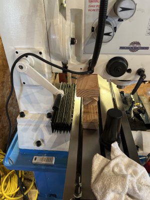
OR....you could buy a power feed with a high torque motor/gearbox, make the adapter place and mount it yourself.... Here is how I did my "Y" axix power feed.
Y axis mod just have to look at how to mount it and what you have to do to adapt a generic power feed.
***99% of what I work on is steel****
For face milling, I use a 2.5" indexable carbide face mill that would bolt up to the 2 ear arbor that came with the mill, and I also use a couple of smallish fly cutters. I need to get a larger one or build one for at least 6".
End mills, 1/2" is about the max I run. I could probably go larger, but 3/8 to 1/2 get the job done for bulk material removal. Feeds and Speeds is the key to it all.
Little Machihne Shop have a nice online calculator that I now have on my phone home page (web link) that is a pretty quick tool for figuring out your feed and speed setting based on the tool and the material.