Needing more than a spark test?

Thank you for thinking of me. I have hopes of getting back into my favourite hobby, but for the present, I have to deal with a debilitating condition, in addition to my wife requiring more surgery next week. Regrettably, I can no longer even fly sailplane gliders, sharing thermals with birds of prey over (UK) Hampshire. To do such stuff, one has to at least be able to climb in!

I take inspiration from you all, folk like @rabler, who has been very kind despite having worse problems than I have. For now, I shall stay with this community, and contribute when I can.
----
When it comes to very low noise front-end high gain stuff, JFE150 and JFE2140 with the low shot noise could indeed be useful, say in the role of the front-end JFET in that extreme performance TIA we have already modeled. I have noticed that many JFETs from the 1990s, often used for high class audio pre-amps, just fit right in when used as part of TIAs working with modern op-amps. Some are simply the same old FET designs, re-named and outrageously priced, offered at the audio fans (eg. those LSK170 and similar from Linear Systems).

By every considered calculation, there seems a reasonable chance that one can achieve low noise gains greater than 1e+05 to compete with photomultipliers. The key property in comparing the two approaches is right up at the sensor. It is about how good are high area PIN diodes vs scintillator crystals feeding PMT photocathodes made of exotic materials.
Graham
Sorry to hear of continuing challenges. It is tough when we have to give up things we love doing. I hope the new year is kinder to us all.
 
I've been doing more work on the power supply for the PMT/scintillator I bought on ebay. Gardening season is fast approaching so I've been trying to move some of these kinds of projects forward before then.

I decided that I needed to make some aluminum boxes to shield the CCFL inverter's electricl mayhem from the low-level control circuitry, and that took a bit of time to educate myself on making boxes. I have a cheap HF 18" brake & discovered it's not all that easy to use right out of the box, so I also made some bits to get the right spacing between the sheet metal and bender. Also some bits to assist in aligning the pieces to as close as 90 degrees to the bend axis -- the brake has no built-in clamps so it is tricky to get the work aligned properly when trying to juggle two degrees of freedom at once. Anyway, I made a couple of boxes with lids, and discovered the advantages of a step drill when it comes to drilling holes in sheet metal.

However, the initial results with the shielding boxes weren't much better than what I observed without them. I decided that the biggest problem was the fact that I was routing 50KHz @1KV from the CCFL to the control box, where the HV rectifiers and capacitors are located. In retrospect that was a recipe for radiating all kinds of EMI. So I worked up a little full-wave bridge and HV capacitor, plus a HV RC filter, on a hunk of vector board, wrapped it with black electrical tape, connected the bridge inputs to the CCFL's output transformer and stuffed it in the CCFL box. That way only low pass-filtered high voltage DC is coming out of the CCFL box. THAT makes all the difference. At least when using channel 2 on my oscilloscope. Channel 1 appears to be significantly noisier. I hadn't noticed that problem because before now I haven't needed to look at 1mv/division signals.

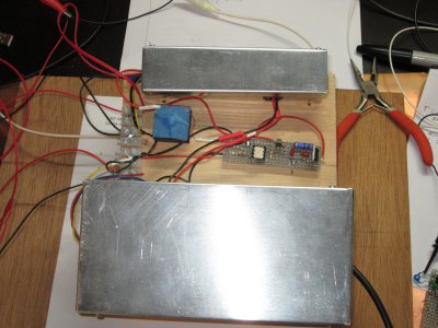
Here's a photo of my current PSU setup:

PSU boxed up.JPG
The thing with the blue tape on it is a home-made choke that helps to block AC from getting into my opto-isolator drive circuit, which is the exposed bit of vector board. The small box contains the CCFL inverter and diode bridge/prefilter board, and the large box contains my control circuity. The black wire coming out of the right side of the box is some RG58 coax that is rated to about 2.5KV. I think folks will know what that's for!

Along the way I also found it necessary to do some surgery on my CCFL board, to get better control over its output voltage and disable its open-lamp fault detection circuitry. If anyone has questions about that, PM me for more details.
 
Can I take it that the hopes of a solid state diode detector for this XRF purpose have been dashed? Or just put on a back burner? Not sure I want to take on a PMT at this time - would be fun, but current responsibilities have definitely reduced some of my play time.
 
Can I take it that the hopes of a solid state diode detector for this XRF purpose have been dashed? Or just put on a back burner? Not sure I want to take on a PMT at this time - would be fun, but current responsibilities have definitely reduced some of my play time.
No, not yet -- but at this point I don't know if I'm not getting spectra due to the detector or my software. I want to use a known-good technology to figure out what's going on. A silicon PIN detector would really be a good solution for a relatively inexpensive and portable XRF setup so I'm still working toward that, but.....need something for a reality/sanity check.
 
the brake has no built-in clamps so it is tricky to get the work aligned properly
I've got a cheap combo brake/shear/roll former that has a weak clamping bar. My go to aluminum is scrap from a sign company. It is too heavy for my brake to get a nice tight bend so I put it on the mill & cut shallow grooves with a V bit. Results in very nice bends & @ 90° to each other due to using the X-Y motion of the mill.
 
I've got a cheap combo brake/shear/roll former that has a weak clamping bar. My go to aluminum is scrap from a sign company. It is too heavy for my brake to get a nice tight bend so I put it on the mill & cut shallow grooves with a V bit. Results in very nice bends & @ 90° to each other due to using the X-Y motion of the mill.
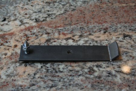
I have used that scheme for putting bends in 1/8" thick steel bar stock. I made a rocker toy that needed a well-controlled bend which used that approach:

IMG_6032.JPG
In use the toy is flipped over so it rocks on the point and shallow arc. The oscillation period can be adjusted by changing the height of the needle point. As shown, it's about 1 second, surprisingly long for how small it is. I based it on a "church key" style can opener I was playing around with.

For the "needing more than a spark test" project it was all about shielding so the .025" aluminum available at my local hardware store was more than sufficient.
 
Can I take it that the hopes of a solid state diode detector for this XRF purpose have been dashed? Or just put on a back burner? Not sure I want to take on a PMT at this time - would be fun, but current responsibilities have definitely reduced some of my play time.
+1 No - not yet. The low noise TIA does appear to work, with gain comparable to PMT tubes. Actually, two of the three candidate circuits seem OK. It is my ADC -> SBC computer interface that still has the fumble. Also, I am following Mark's posts, because I also have a PMT tube and scintillator, but that one is parked on the shelf for now. It's an ex-Soviet new old stock I got from an eBay seller in Ukraine.

The TNA has to be shielded from local 50/60 HZ magnetic fields, have pristine clean power that does not share return current paths with any other electronics. Electric field shielding is relatively easy. Magnetic is not. Thus, my amplifier has the 60/60Hz rejection stage. Using battery cells to bias the PIN diode was also the easiest way to get a guaranteed clean supply.

I have not yet checked if the photodiodes we were trying out are still available, nor whether any better candidates are now around. Sure, there are exotic expensive large area PIN diodes to be had, but what drove the choice for me was when Mark found the low-cost version in a counter product.
------------------------------------
In this, and indeed with all other things I get up to, it all went on pause while I kind of ceased to function properly. I am now on steroid immuno-suppression medication, and somewhat returning to "normal", though I can tell the demon is still in my space. Still to be properly diagnosed, but I now have the blessed relief that I can at least move about again. If/when I get the TIA hooting, I will let you know.
 
Last edited:
About clock jitter.
This is well into the weeds about 16-bit ADCs, but now I begin to think that casual SB computers, Pis, Raspberry Pico or other digital clocks have too much jitter and other noise to be good for ADC sampling. For computing, they are fine, because the logic settles between pulses, but the ADC sampling relies on a threshold being passed at the same level, and at the regular instant, on a waveform being sampled. If there is noise on the any of it, whether in the amplitude, or in the phase, you get a jangled spread of numbers.

The thing is quite sensitive to sample clock jitter, because if the rise time of the pulse being sampled is a bit fast, say in a waveform where the entire duration is 13uS, then the phase noise in the clock is going to cause samples at all sorts of voltages up and down around the right place.

So - I have to put that one aside for a bit. Maybe I can have a nice, low-jitter clock, and just use it to externally clock everything. It may not matter for data being fetched from the ADC, but I think the ADC may have to be given something with less phase noise.

There must be some cheap-n-cheerful crystal clocks with low phase noise, so we look around for a bit.
 
Regarding the question about the availability of the X100-7 x-ray detector, I found that Sparkfun has discontinued it. Robotshop.com claims to carry it, but it's currently backordered -- and the source is Sparkfun, so availability there is a strong "maybe not". They also are asking $91.25 not including shipping.

Interestingly enough, Mouser offers a version that includes a CsI(Tl) scintillator. The scintillator bumps the price up to a bit less than $124 -- and it's currently backordered. The X100-7 w/o a scintillator is no longer available via Mouser.

As a potential alternative, I note that Mouser has a number of SiPM detector chips. They have a 3x3mm for $29.21 and a 4x4 for $34.70. Combine that with one of these and you've got a more mainstream type of detector for less than what I paid for my pocket geiger. This particular CsI(Tl) crystal already is coated with highly reflective paint to direct more photons into the detector. The front end electronics would be very similar to what's been discussed for the X100-7, including the bias generator.

These SiPM's come in micro BGA packages, which would be an issue for many DIYers. But the parts supplier arm of EasyEDA offers the 3x3, which means that interested parties could order PCBs that already have the SiPM installed. They do tack on an additional ~$5 compared to Mouser but that's cheap compared to the base price if you screw it up....
 
@graham-xrf , half decent crystal oscillators are available for not too much cash. We used them in automotive radars, so they had to be very inexpensive. We used 16 bit converters. Although ADC's are sensitive to clock noise, quite often, it is usually not the clock which is the dominant noise contributor.

Often it was a poor front end, or even sloppy signal processing that lead to the classic, "we are 10 dB worse than we ought to be". (I've seen far worse on some systems.) Obviously, not saying something you don't know, but thought I'd point it out to others (if anyone is still following). I've had many occasions to install extremely low phase noise oscillators into systems and saw no difference. It should have helped, in theory, but the dominant noise contributors were far, far greater and swamped the contribution of the oscillator, so there was no detectable difference, even in a statistical sense over > 10,000 trials. In one case, it was a bitter pill for the software team to swallow, since in fact it was their algorithms that were degrading the SNR, not the oscillator. Once those algorithms were identified, they were changed and we achieved predicted performance.

An ADC triggered synchronously via a quality time base, typically a crystal oscillator, with quality clock drivers, usually gives very good results. If a processor triggers it, well that's really not going to work. The data collection can be processor driven, and have some jitter, but not the trigger. Some processors even dither their clock, so they will pass emissions standards, the dither simply introduces noise into the trigger, which in turn injects noise into the sampled data.
 
Back
Top