I really don't use PayPal either. Mine is not tied to my bank account (which I think is nuts) but to my CC. The CC companies dwarf PayPal so they provide me protection for stuff gone bad. I rarely use PayPal, to be honest. But I did use it twice here at Hobby Machinist. First for a gold membership here, then a year later to make a single lifetime payment. Seemed worth it to me anyways.
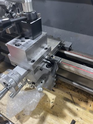
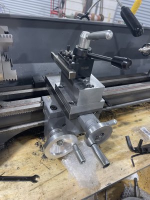
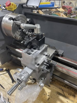
Having 6 nuts to tighten isn't that much fun, but it beats having the compound moving. It has been a very worthwhile modification for my lathe.