Mitsubishi Vfd - Wiring - Can't Figure It Out.

middle.road

Granite Stoopid...
H-M Supporter Gold Member
Joined
Apr 28, 2014
Messages
3,590
Hey gang!
I need some help connecting the dots. I am a tad lost trying to wire up the Mitsu VFD. (Completely actually.)
I do wish that I understood electrical systems and schematics better.

I finally got the garage re-wired and dropped a new circuit of 10/4 over to the mill.

I'm trying to layout all the wiring and then make up the mounts and harness(es) as required.

- VFD is a Mitsubishi FR-D7205-070-NA.
- Motor on the Bridgeport is wired for 240v.
- I would like to keep the drum switch (just because old habits die hard...)
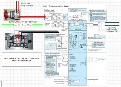
- I'm adding a 'Panic button'. to the two hots coming from the sub-panel before they connect to the VFD.

Would anyone hazard a guess as to how I should connect the three wires from the Bridgeport motor to
the 'U', 'V', & 'W'? There were Black, Red and White coming from the motor to the drum switch.

I've poured over dozens of diagrams on the web and can't figure out how to wire up this VFD for the drum switch.
I'm figuring that it has to with the 'STF', 'STR', & '???' (maybe the 'SD')

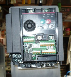
I also need to know how the green/orange connectors on the the front work, I've never seen this type before.
I'm assuming it's just push the wire in, and then use the orange bar to release, but again my confidence level is pretty low.

Thanks in advance, _Dan
Mitsu_BP_Wiring_Diagram_02.jpg Mitsu_D720_Frt_Conn_01.jpg
 
Hi Dan,

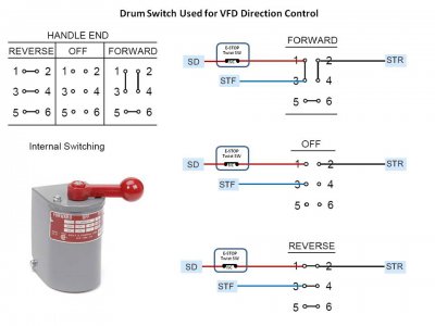
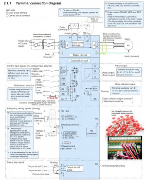
A few suggestions and diagrams for you to review. I would use a standard 2 pole 240V power disconnect switch for power to the VFD, and use a breaker or cartridge fuse for L1 and L2 unless you have a dedicated circuit with a breaker at the box/sub panel. Power is connected to the L1 and L2 terminal in the VFD. The E-stop switch should not be in the input power to the VFD, but should be used to interrupts the low voltage power that operates the input commands. So SD would connect to the E-Stop and then continue to connect to the drum switch. The drum switch would ONLY switch the low voltage control signal to the forward STF and the reverse STR terminal based on the position of the drum switch. You use pin connection terminals on the end of your control wires (usually 18-22G) that push into the terminals on the VFD. The small orange button above each pin insertion hole is pushed in with a small screwdriver and the pin pulled on to remove the pin. The pins require a special crimp that crushes them in a circle, I end up stripping the wire and inserting it into the pin so the wire sticks a little out the other end, and quickly solder the tip so the solder runs into the tube and then clip off the extra wire. Too much heat and you will melt the plastic collar.

The VFD is connected directly to the VFD, so the motor must be 3 phase and the U, V, W is connected directly to the motor terminals, and a ground wire. So you should use 14/4 wire preferably shielded. The drain wire for the shield is only connected at the VFD end. The control wires should be at least 6" away from the motor cable, to prevent induction cause false signaling. If your motor is running the wrong direction, switch any two of the 3 phase wires at either the motor or the VFD.
http://www.ebay.com/itm/30-FEET-LAP...RSIBLE-PUMP-/191591216501?hash=item2c9bb9f575
http://www.sabcable.com/new_data/VFD_Whitepaper.pdfDrum Switch Used for VFD Direction Control.jpg VFD Connection Schematic.jpg
 
Thanks for the quick reply M.
The 10/4 is on it's own breaker, strictly for the mill & to power an outlet for the DRO.
Well those 'connectors' are sure a show stopper. I pulled out one of the jumpers and I have to say, I've never seen that one.
Measures ~ .045 x .062. I don't believe I understand the reasoning behind a rectangle connector, why now use a screw down type?
I'm going to have to improvise something. That's one crimp tool I don't have and I can't afford to buy that one for just a few connections.

I think I should have gone with a Teco or an Hitachi. I was shopping price...
I'm not sure how I'm going to get the control wires spaced 6" from the motor wires, there's only an inch or so between them.
Of all the wire I have laying around I don't have any large gauge shielded.
I'll have to run out tomorrow and see what I can find. Around here that might be a trick. I wish I'd been sharp enough to order supplies
a couple of months ago. This puppy has been sitting waiting to be used since May.
 
Well those 'connectors' are sure a show stopper. I pulled out one of the jumpers and I have to say, I've never seen that one.
Measures ~ .045 x .062. I don't believe I understand the reasoning behind a rectangle connector, why now use a screw down type?
I'm going to have to improvise something. That's one crimp tool I don't have and I can't afford to buy that one for just a few connections.


I have one of those crimpers and they ain't cheap. About $140 if I remember correctly and that was 20 years ago. You can just stuff a stranded wire in those connectors, works just fine.
 
I do not understand why you would want to use a drum switch in this application. A drum switch is intended to switch line voltage conductors directly to the motor. What was shown by mksj will certainly work but seems like a case of gigantic over kill to me. The job of switching the stop output wire to the forward and reverse inputs can simply be done with an inexpensive double throw single pole maintained switch with center OFF.

If you purchase some 22mm control switches and use a push to stop/twist to release switch it will also give you a safety lockout of sorts. Then use a three position maintained switch to as a FORWARD-OFF-REVERSE control. Enclosures and switch labels are premade for this application and from the same source as the switches. To wire connect SD to the STOP pushbutton, then a common wire to the three position switch. Then from one side of the switch to STF for FORWARD and to STR for REVERSE. These switches only switch low voltage control signals and the recommended switch will duplicate the manual operation of the drum switch for hand feel. To feel more like a drum switch ask for an extended handle for glove operation. These buttons will easily mount in place of the drum switch.

Please, under no circumstances interrupt the wires between the VFD and the motor. Serious damage will result. I am going to make the wild assumption that you are connecting to a 2hp motor on the Bridgeport. By the book motor load is 6.8 amps so #14 wire from the VFD to the motor will suffice. These will connect from U, V, W, to motor leads 1 & 7, 2 & 8, and 3 & 9, with 4, 5, & 6, twisted together. As long as the run is short, metal flex conduit will substitute for shielded wire. If you purchase shielded cable be careful to watch the voltage rating on the cable is good for at least 300 volts. Most computer type wire is NOT.

Have fun. Get that puppy making SWARF! :aok:
 
Hi Dan,

Mitsubishi makes very fine drives, unfortunately VFD's are very difficult to set up, even for experienced electricians. Do you have the 33 page Installation Guide or the 300 page Instruction Manual? No, I'm not kidding, they can be downloaded and can give you some guidance. The UVW terminals are for the 208 volt three phase motor leads in any order. Normally, you would not have a white lead except on a single phase motor. If it is a single phase motor, do not connect it without further instruction. Never connect any other leads to UVW other than the motor leads.
The diagram mksj posted has everything you need for "Start Forward" and "Start Reverse" the SD is the switch common line for direction and speed range switches.
The Phoenix terminals do not require a blade terminal, as long as you are using solid or stranded wire of the correct gauge wire. If you use stranded wire, be very careful to twist it tightly, as to not let any strands escape and short out the nearby terminal. They also sell crimp on pin terminals that don't require a special crimper, which is what I use. Do not solder a stranded wire as a substitute for a solid wire. Use a 3/32" screwdriver to push down the orange open/close button while inserting the wire.
I can't add any links as I have not made enough posts.

Randy
 
Last edited:
I have one of those crimpers and they ain't cheap. About $140 if I remember correctly and that was 20 years ago. You can just stuff a stranded wire in those connectors, works just fine.

FORGOT!!!! Yes those crimpers are expensive, but very necessary to use these termination ferules. Our experience in a custom control shop has been that the small screws in the terminal strip will not put adequate pressure to deform the ferule and hold the wire without a crimp. The next event is the wire comes out just enough to create an intermittent open in the circuit a trouble shooting nightmare. In your application I would just run #16 or #18 for the control conductors and forget the ferules. Also the ferules come 100 in a bag and are not cheap. But a cabinet totally made up with them does look cool.

Now back to the SWARF manufacturing. :+1:
 
.................... unfortunately VFD's are very difficult to set up, even for experienced electricians.

I would submit that the VFDs are easy to setup, but translating the poor translation in the manual is the difficult part. For the most part there are very few parameters that need to be set to get up and running. Most VFDs have 100 or more parameters, but you only need about 5 of them to get going. Most of it is not useful unless you have a special application. If the manuals would give the basic setup in the first pages, life would be much easier. Having to wade through all of the parameter descriptions to setup is just wrong.
.
.
 
Thanks for all the replies gang! Reading over them with the first cup of coffee gives me hope this fine day.

The reason for a Drum Switch is strictly a second nature 'old habits' / instinct type of thing. So many years of running mills with one at your left hand
ingrains a habit that is hard to retrain. Like on my Birmingham lathe, after two years and I'm still not use to the lever on the carriage. I keep messing that up.
(My father worked for Furnas Electric when I was young. I had a box full of switches and stuff that we use to 'play' with. Maybe that's why. <GRIN>)

Thankfully the motor is wired up as noted above by RD. The Black/Red/White I mentioned was just the SO cable running to the drum switch.

Can't find any 14/4 shielded within a 25 mile radius. So I'm going to try some flex. (I'll wrap the wires in copper foil tape, and toss on a coat of aluminum paint :D )
Late last night, I shaved .010" off top & bottom of some 14ga solid THWN. So that matches the cross section of the connectors.

Geek action: I know I've got an RS-232 / RS-485 cable around here somewhere. Need to find that. Would a computer make it easier to program this VFD?

Again, thanks for all the info guys, off into the shop.
 
Back
Top