-
Welcome back Guest! Did you know you can mentor other members here at H-M? If not, please check out our Relaunch of Hobby Machinist Mentoring Program!
You are using an out of date browser. It may not display this or other websites correctly.
You should upgrade or use an alternative browser.
You should upgrade or use an alternative browser.
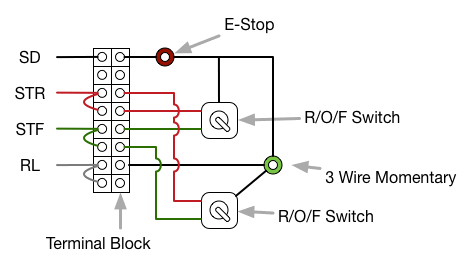
Mitsubishi Vfd - Wiring - Can't Figure It Out.
- Thread starter middle.road
- Start date
- Joined
- Jun 12, 2014
- Messages
- 4,812
The diodes are dirt cheap and available on eBay, Mouser or any electronics house. About any diode will work, it is like a check valve only allowing the voltage to travel one direction. The band side is the forward direction and would be closest to the terminal block
http://www.ebay.com/itm/UF4007-Ultr...387392?hash=item4af43f9480:g:owoAAOSw5VFWJnvJ
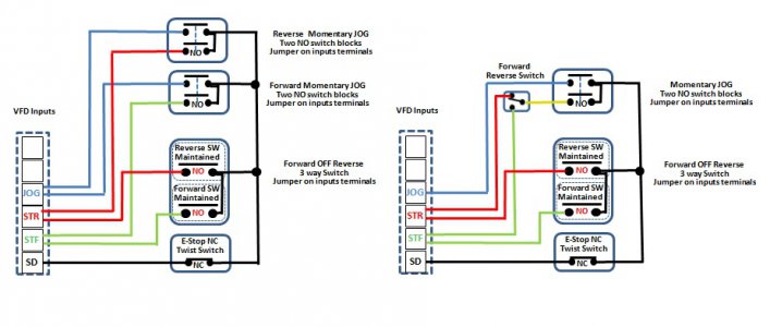
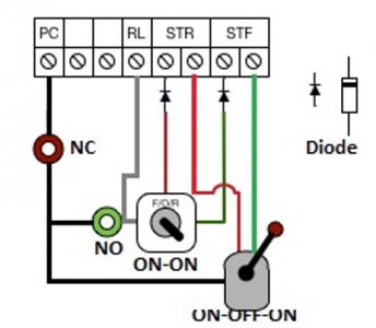
But if no diodes then this schematic should work fine. One uses a JOG Forward and JOG Reverse, the other uses a single JOG button and a direction toggle switch. Most push button switches come with a single NO control switch block, you can buy them and add a second to the switch.
http://www.automationdirect.com/adc...inated_Pushbuttons_Flush_-a-_Extended/GCX1104
http://www.automationdirect.com/adc...shbutton_Accessories/Contact_Blocks/ECX1040-2

- Joined
- Jun 12, 2014
- Messages
- 4,812
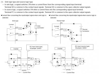
To use diodes as shown previously the VFDs inputs internal logic jumper is set to source logic and instead of using SD for the common, PC is used. This means power flows from PC (+) to the switches and then to the respective input which is at 0V (-). This requires using the PC terminal (wire goes to the E-Stop then switches) and the VFD logic switch set to source from my read of the schematic.

- Joined
- Nov 16, 2015
- Messages
- 25
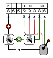
So...Not to flog a dead horse here, but based on this, once i move the jumper from sink to source, assuming i had it wired as per the image below i should be in business? Note: the 3 position switch in the middle supports 4 poles NO with any 2 poles connected in either of the two closed positions. So, I would have STR+PC and JOG+PC to the left, and STF+PC and JOG+PC to the right with the middle being OFF.
Much thanks for sticking with me. I know I'm a bit think in the head, not to mention the mid section!

Much thanks for sticking with me. I know I'm a bit think in the head, not to mention the mid section!
- Joined
- Jun 12, 2014
- Messages
- 4,812
Needed my glasses for that picture. Its hard to grasp some of the concepts until you start doing it, I had a few pumps in the road learning about these things. You just need two diodes as shown, the banded end goes toward the terminal which is the direction of the current (signal). RL needs to be programmed to JOG function. The purpose of the diode as mentioned is like a valve, it allows a current (signal) in one direction and not the reverse, always from the + to - direction. This is why you need source logic so PC is the + terminal. So when you press the JOG button it makes contact with the RL terminal and allows the forward/reverse command terminal to be activated. When you operate the forward/reverse via the lever control, the current (signal) cannot travel backwards through the diode. If the diodes were not there, current would travel back through the jog for/rev switch to the RL terminal and you would only get jog speed. So no changes to your current wiring for the lever control switch. Connect another wire from your E-Stop to one side of your NO jog switch, connect the other terminal to RL, and the input (center) of a ON ON switch to switch from forward to reverse. Connect one output to STR with a diode anywhere inline as shown, connect the other output with a diode anywhere inline as shown. QED.

Last edited:
- Joined
- Apr 28, 2014
- Messages
- 3,590
You gotta admit, the assistance on this forum board is second to none!


