New Caretaker of Two 12” Craftsman Lathes

Back at it. I reconsidered my previous plan to mount the backsplash on the wall and opted to mount it on the lathe cabinet. I figured forever is a long-long time and I may want to move the location of the lathe at some point and by the time I fabbed the features to mount and position it on the wall, it wasn’t much more effort to make everything an integral unit. So I bent up some 18 gage ribbing and mounting flanges and stitched it to the backside of the backsplash to stiffen it up and provide some mounting points.
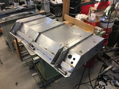
77 BS Ribbing.JPG

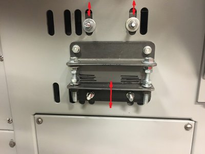
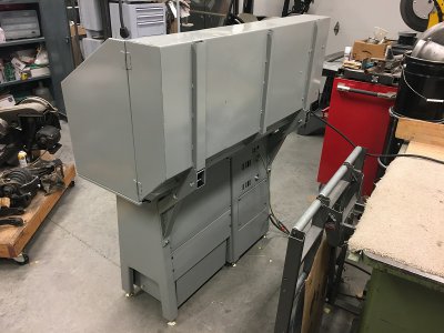
For the mounting brackets I had some short 2” square tube remnants and figured with ¼” mounting plates and some 1/8” gussets would get the backsplash mounting job done. They mount on pedestal and end cap of the cabinet which are 3/16” formed steel, so they are a good rigid attaching location. I painted everything the same as the lathe and cabinet. …..onto final assembly.
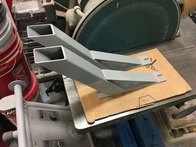
78 BS Mounts.JPG
79 BS Rear Mounted.JPG
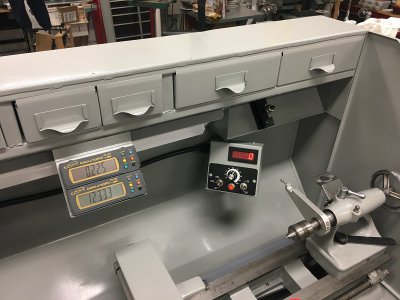
I mounted the electrical components and wired everything up. Besides the VFD, it’s just a few switches and connectors, and small power supply for the tach and DROs……The cables and harnesses to connect everything took some effort, especially the remote VFS control box, but it’s clean, functions and presents well.
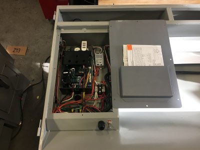
80 Electrical Box Wired.JPG

I installed a panic button. The VFD had an emergency stop capability with rapid motor deceleration so I figured what the heck, why not…..?
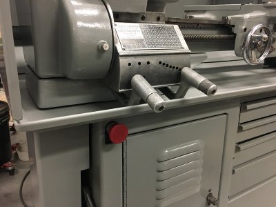
81  eStop.JPG

The back underside of the control box portion of the backsplash has receptacles to receive plugs from the motor, tachometer sensor, and emergency stop in the lower cabinet.
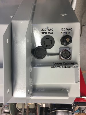
82 Service Outlets.JPG

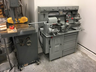
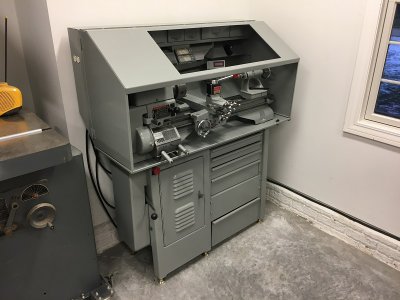
Since I’m standing at a distance you can see the light itself in the picture but when you are standing at the lathe it shines on the work area and line of sight to your eyes is shielded by the deflector.
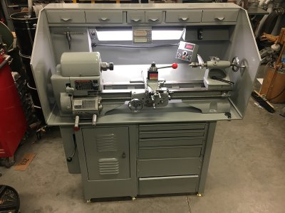
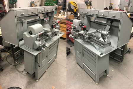
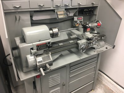
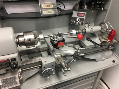
83 Front.JPG
84 Qtr Views.JPG
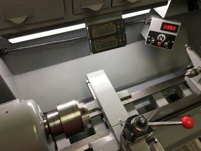
85 Displays.JPG

I bench tested the 3-phase motor but need to mount it in the cabinet. Should get to that tomorrow. Getting’ close to wrapping this one up.

Best,
Kelly
 
That looks quite nice. Nearly 40 years ago, I did something vaguely similar on my 3996. Mine is rigidly attached to the cabinet and drip pan. Other practical differences are that the left end or the backsplash stops even with the right end of the headstock and the right end of the backsplash doesn't come forward as far as the tailstock. I've done some work on parts longer than 36"by removing the tailstock and supporting the right end of the work with the steady rest. Plus I have the lever-operated tailstock that I have used a couple or times. And the tailstock turret which I haven't actually used but could.
 
That cabinet looks great. All it needs are chips and oil all over it and it'll be finished!
 
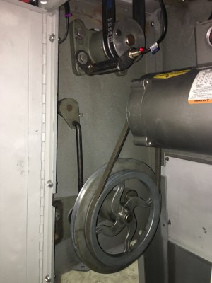
Thanks for the comments and likes fellas. Much appreciated. Mounted the 3-phase motor in the cabinet and wired it up along with the emergency stop and tach sensor. Made a motor adjuster out of some angle iron scraps for it for belt tensioning. The lathe will be backed up to a wall but should be easy enough to change and tension belts now.

86 Motor Adjuster.JPG

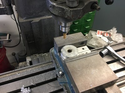
Getting the tach sensor mounted took more effort than I had planned. I ended up just pulling the upper bearing/pillow block and pulley assembly out of the cabinet. Pulled the 2-groove pulley off and spotfaced a dot on the pulley face to mount the magnetic pick-up for the tachometer sensor.

87 Pulley Magnet.JPG

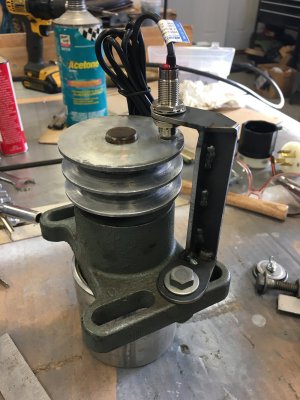
Then I went to my scrap bucket and pieced together a mount for the tach sensor.

88 Sensor Mount.JPG

Here it is mounted in the cabinet.

89 Sensor In Cabinet.JPG

Couple small details to tie up but happy to say everything works as intended. Now I have to clear out its new shop location, level it, start dialing it in, and call it a wrap.

Best,
Kelly
 
Last edited:
Been a while so thought I’d post an update. Everything is working fine except if I try to run the DRO from a power supply rather than the battery. The VFD is a source EMI/RFI and I chased my tail for a while with that……..


I’m going to put a filter on the VFD power inlet but wanted to finish setting the machine up. I leveled the cabinet because my floor has drainage grade and then started on the lathe bed. I only have Starret 98 so I didn’t spend a lot of time there but got it as level as could with the .005/ft resolution….only took one shimming adjustment.

I had a piece of 5/8 linear race rod left over from an old (as in 15+ years ago) project it’s 1ft long, and rounder and more consistent diameter than I can measure. I laid it on my surface plate, put my phone spot light behind, got down to the surface where the rod contacted was eye level, and could occasionally just barely catch a glimpse of leaking light at the surface as I rolled it……so I figure it’s pretty darn straight too.

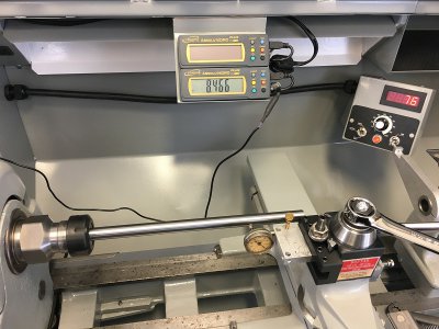
So I chucked it in the ER-32 collet chuck and was getting quite a bit of variation every time I rechecked.

1 Test Bar.JPG

So I grabbed by best small 3-jaw and it was better. In fact, using the averaging method, with 2” of rod in the chuck, I was at ~.001” run out at the chuck and about .004” at 10” down the test bar, but the headstock was slightly askew about .006” at 10” down the test bar. So I loosened the rear mounting bolts on the head stock and after some tapping and wrapping with a lead hammer, I had about the same at the chuck and registering -.001 to +.003 at 10”. I figured that meant I was within .001 of the headstock being straight and only a couple thou run out at 10”…..and thought that was darn good. This all in the horizontal plane. So I put the dial on top the rod and checked at the chuck and 10”.

2 Test Bar.JPG

Less run out than I could measure at the chuck and got plus +.003 to -.001 at 10” so headstock is just a hair nose up…..but I think that is a stroke of luck without additional shimming and the crude initial set up, so I quit while I was ahead.

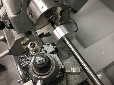
So I chucked and center drilled both ends of the test bar, trued the countersink with a tiny boring bar, and pressed a couple 2” diameter by 1” wide aluminum pucks on the test bar leaving a chucking stub on one end. I mounted a sharp bit, made one clean up pass, and then a .002” clean up cut, and they are .001” off over 10”.

3 Test Bar.JPG
4 Test Bard.JPG

I think I’m going to make a dedicated drive dog for it, so I can set it up between centers, and we’ll see how well I did on the test bar centers, but it’s close enough for me.

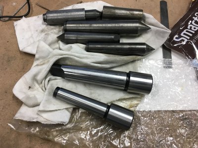
I also bought these cheap MT3 and MT2 mandrels; $25 delivered for both. They are cheap Amazon Chinesium but are actually better than I expected.

5 MT Stubs.JPG

They have 25mm soft stubs. I was thinking I’d machine the stubs and compare them to the 2-collar test bar. They had a few nicks on the tapers that easily stoned down. They are supposed to be soft only on the mandrel and case hardened everywhere else, but I suspect they are pretty soft everywhere based on how easily the tapers stoned. Afterward, they showed .003 run out on the stub, but nothing on the exposed portion of the taper. I marked the high spot on the stub and they very consistently remounted in the taper. The convenient thing about these is you could test anywhere along the length lathe bed.

It’s getting to be time for me to machine those drive pulleys I cast.

Best,
Kelly
 
Last edited:
Wow... All I can say is "Wow".....

First of all, you are a very talented person.
Second, THANK you for posting this thread. You've got me excited about putting a DRO on my 1940's 54" Craftsman... I never realized how 'simple' it was, relatively speaking...
Third, you CLEARLY should not have retired. You love this stuff too much!
Fourth - You need to consider making parts. Your ability to make castings of long-since unavailable parts can help breath new life into many an old machine. I don't know how difficult or expensive it is to make some of these items, but please consider it. I personally would be interested in the 'back extension' for the cross slide. That's WAY beyond what I could make... Mine would be a cobbled together clampy-thingy for sure.

Keep up the good work and please continue to post as much as you can about your upcoming projects. I for one will certainly be checking for any new posts from you...

Thanks

-Mike
 
Back
Top