Receiving and setting up a new Precision Matthews PM1054TV 3 phase mill

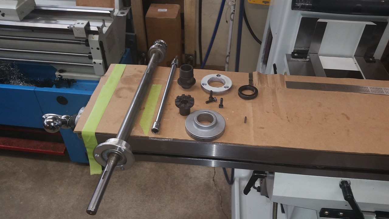
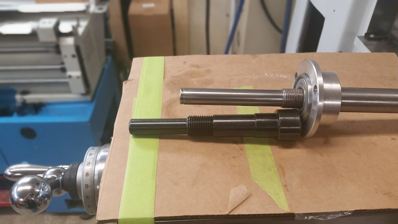
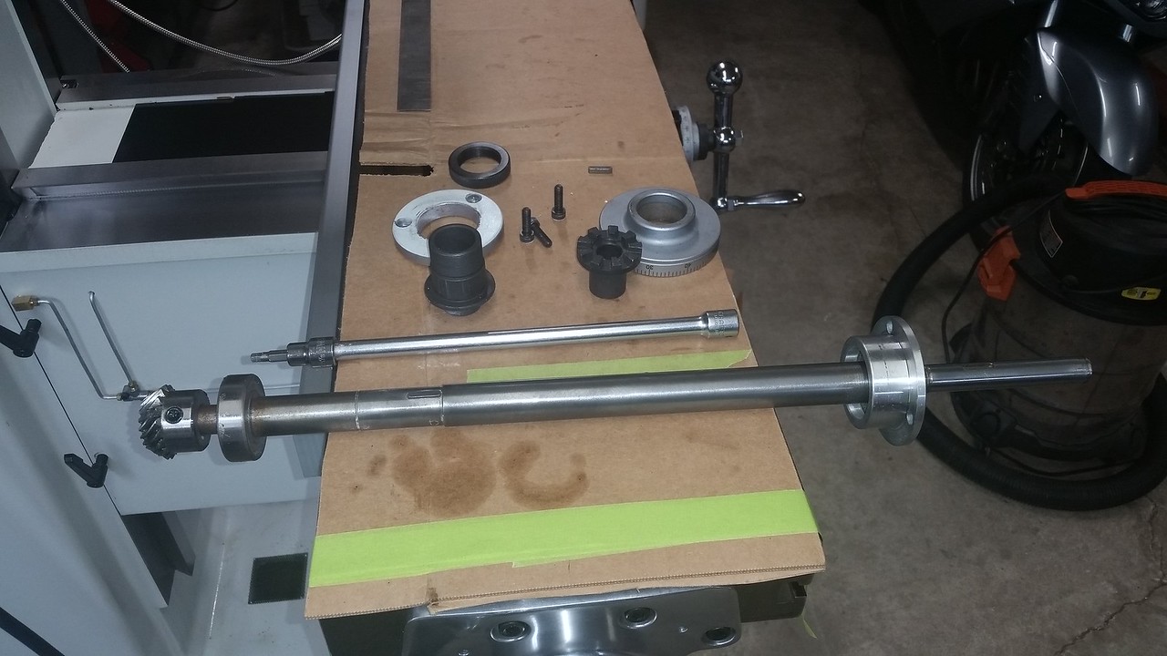
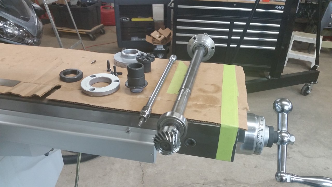
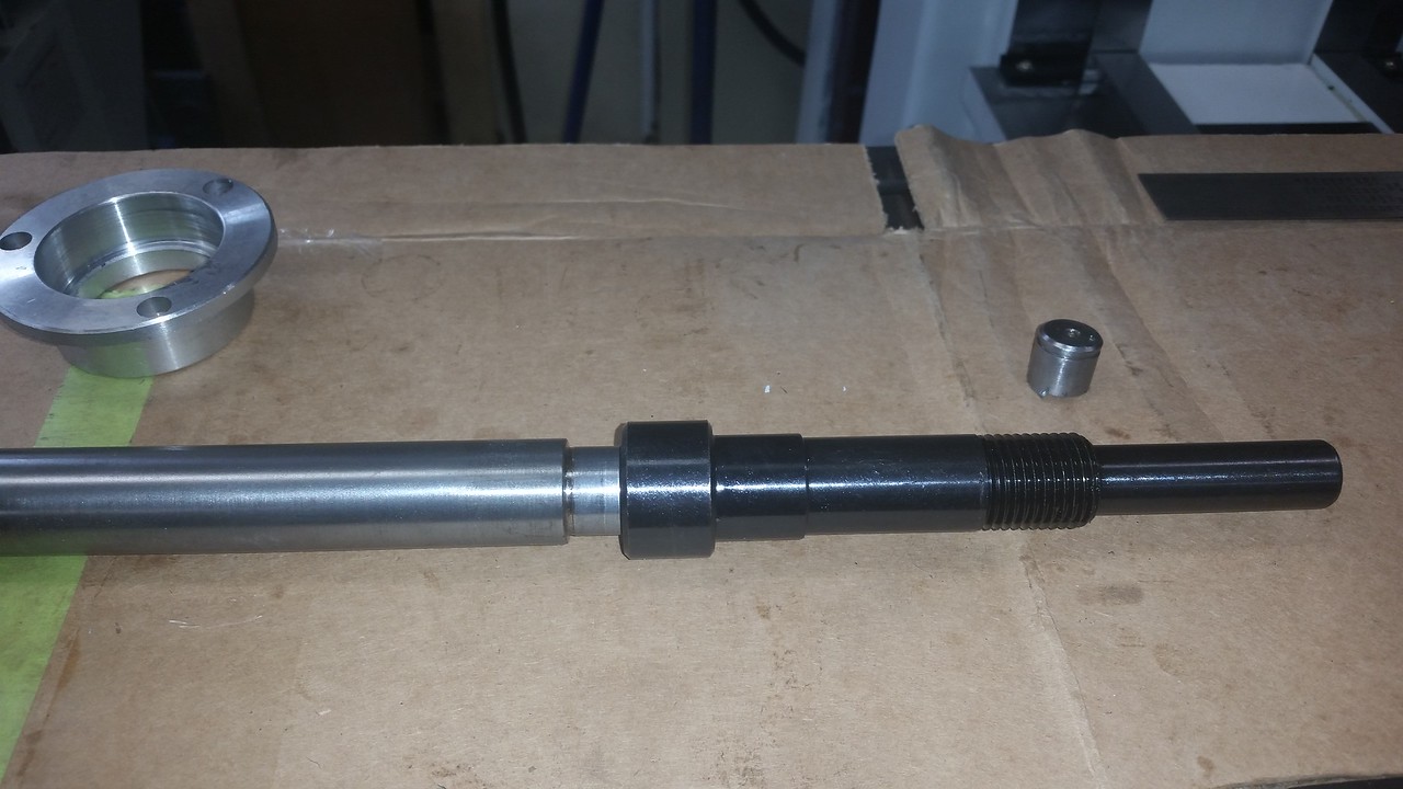
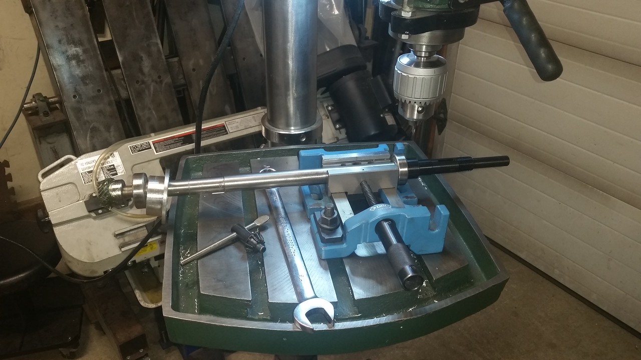
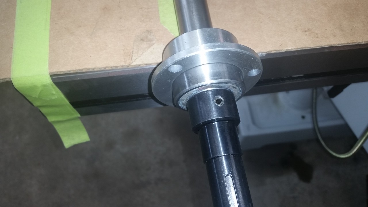
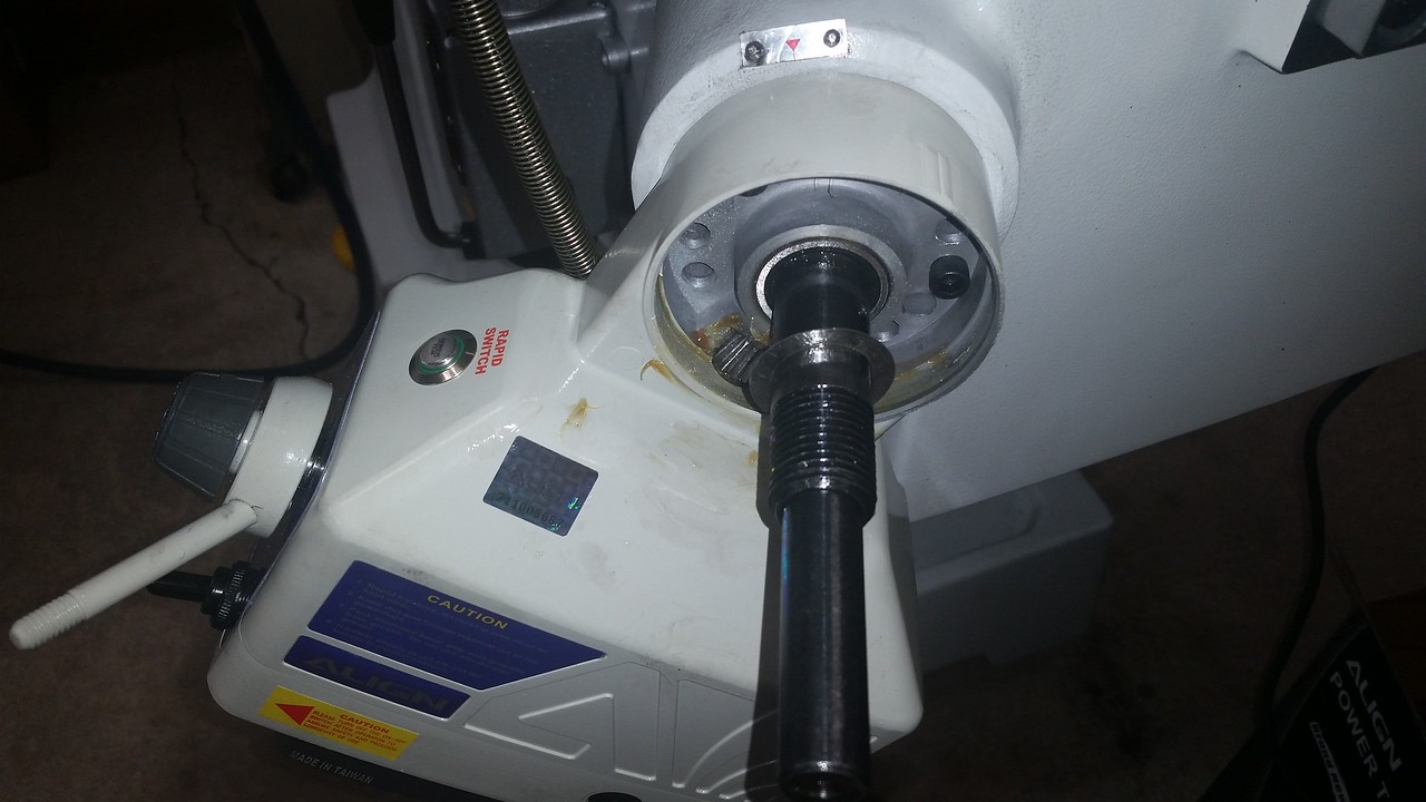
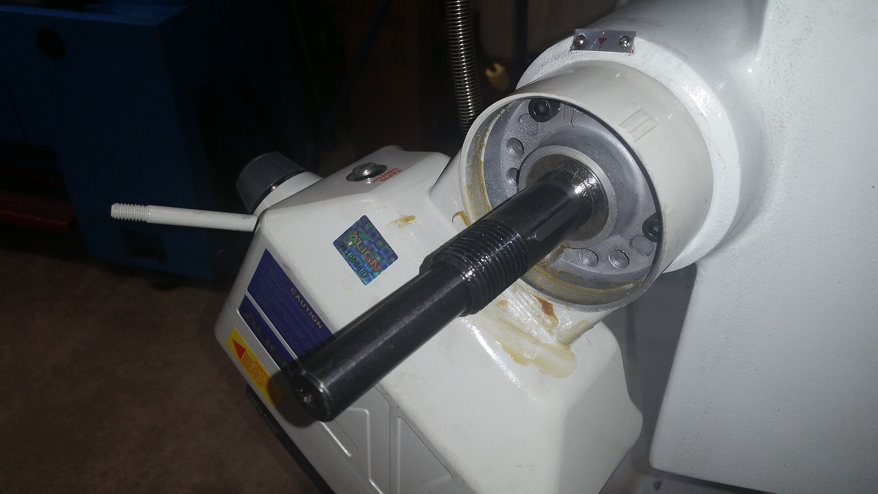
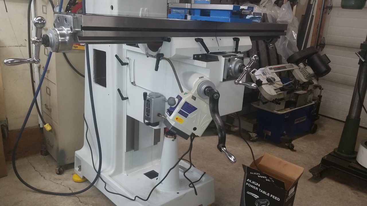
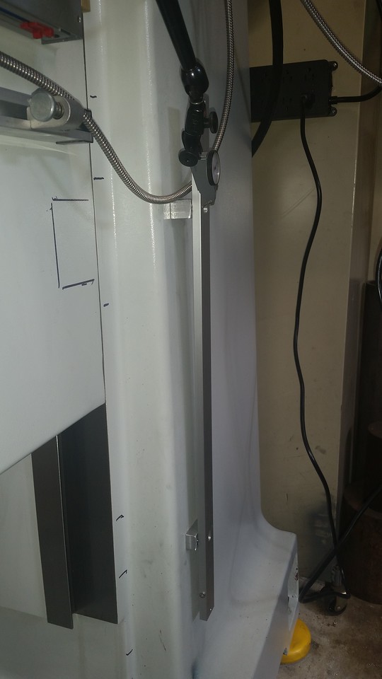
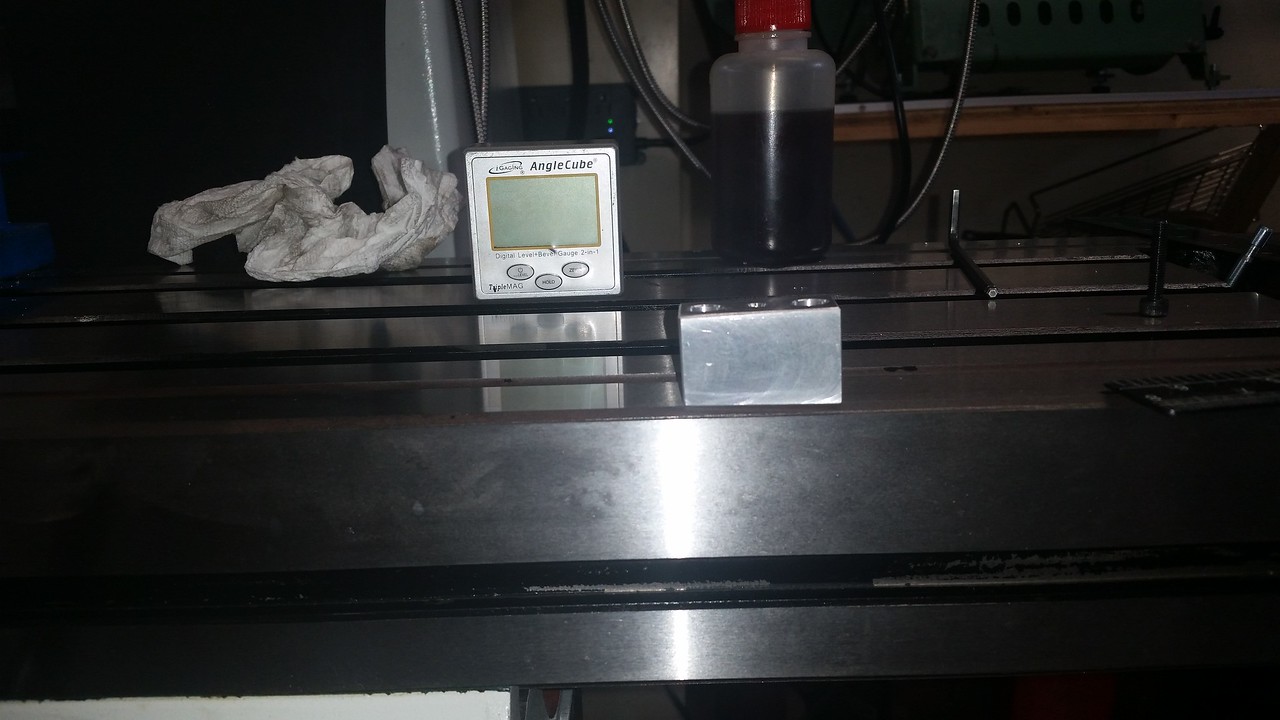
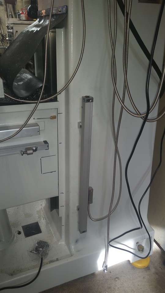
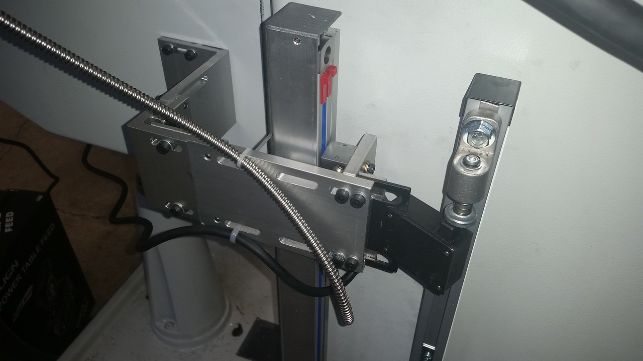
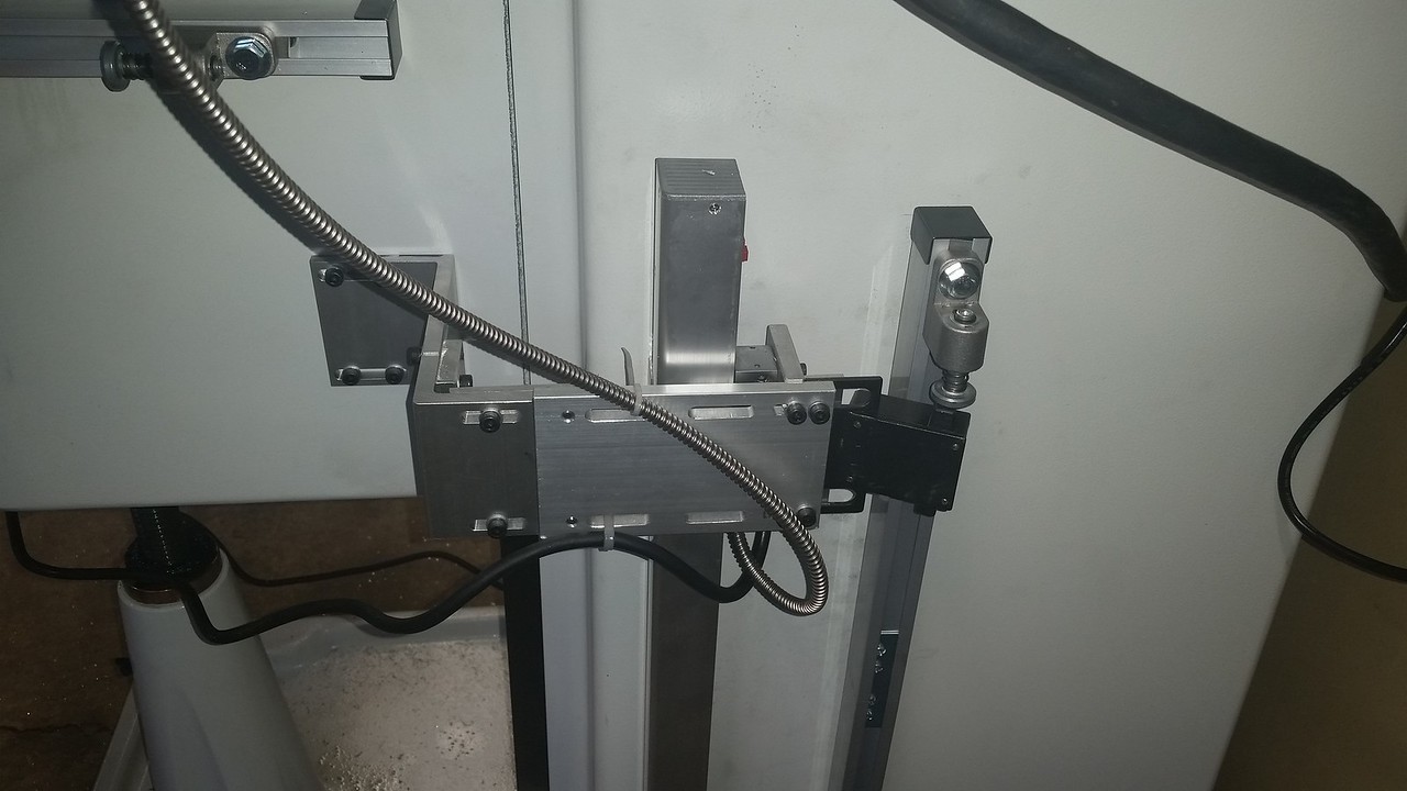
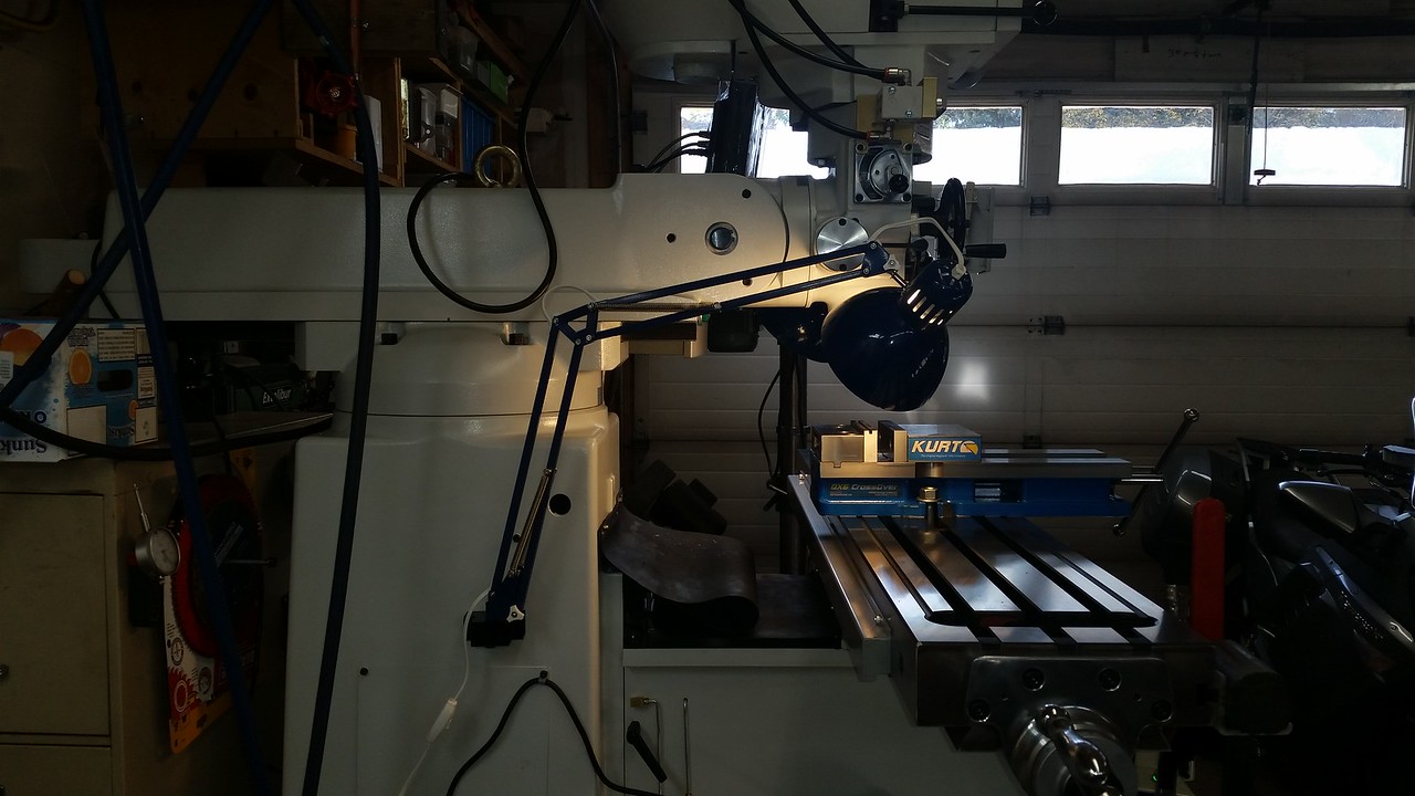
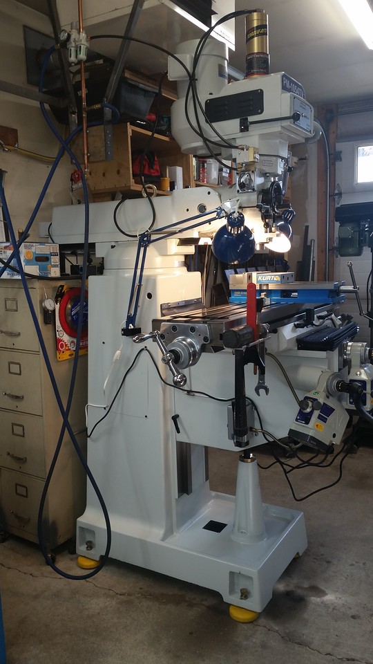
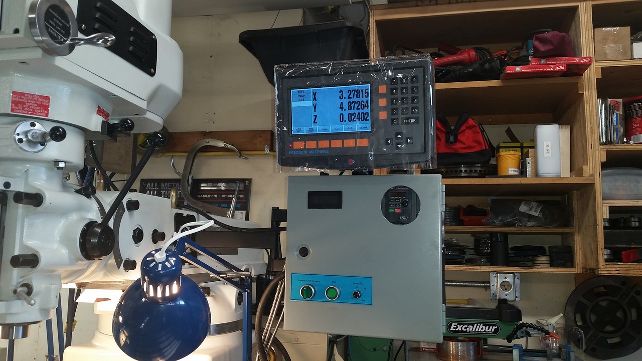
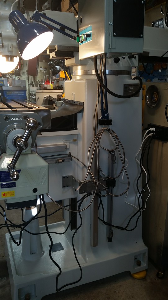
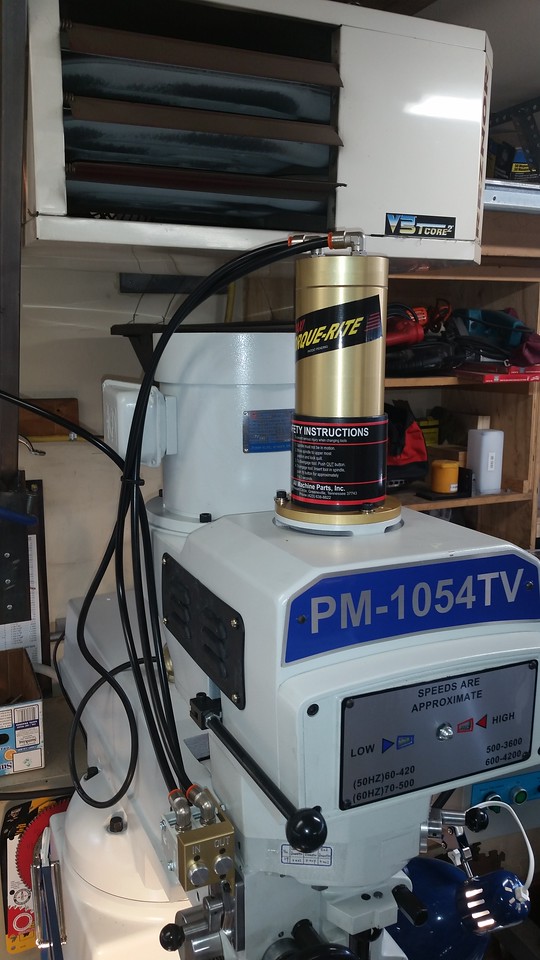
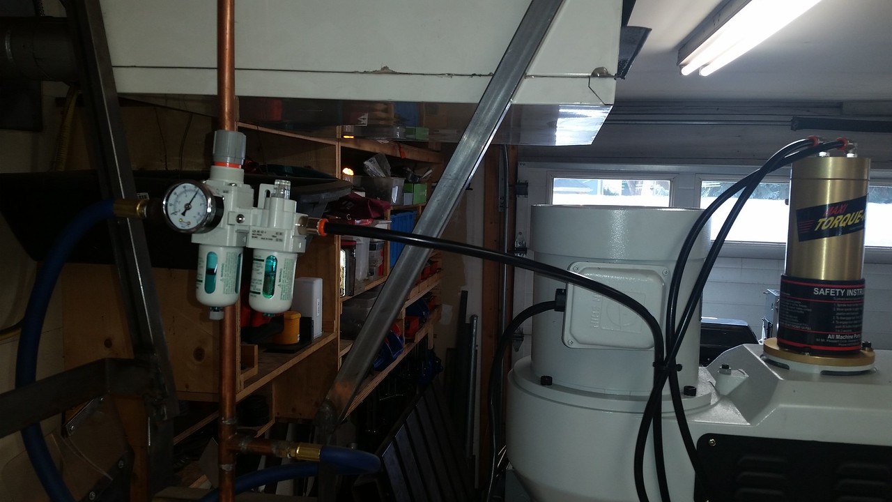
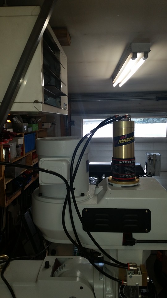
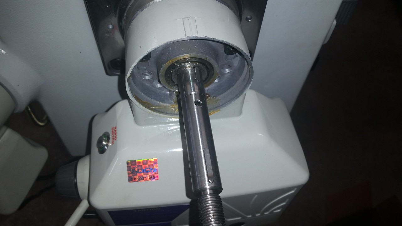
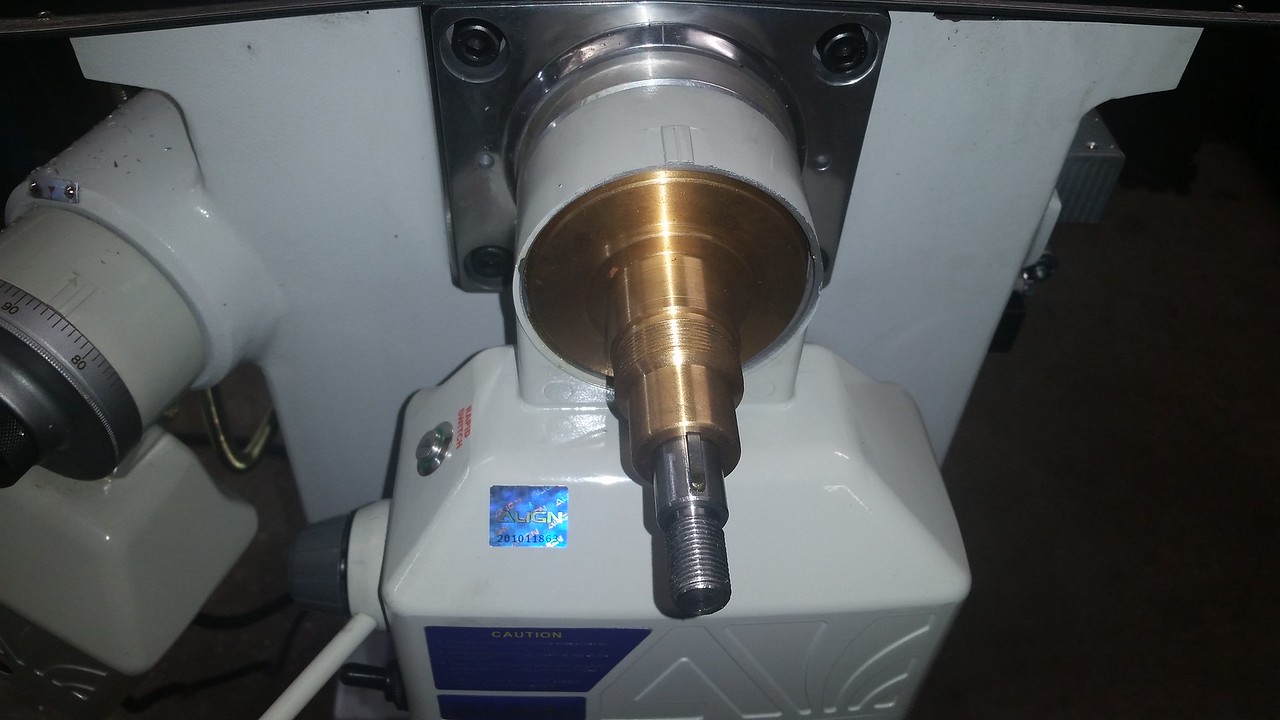
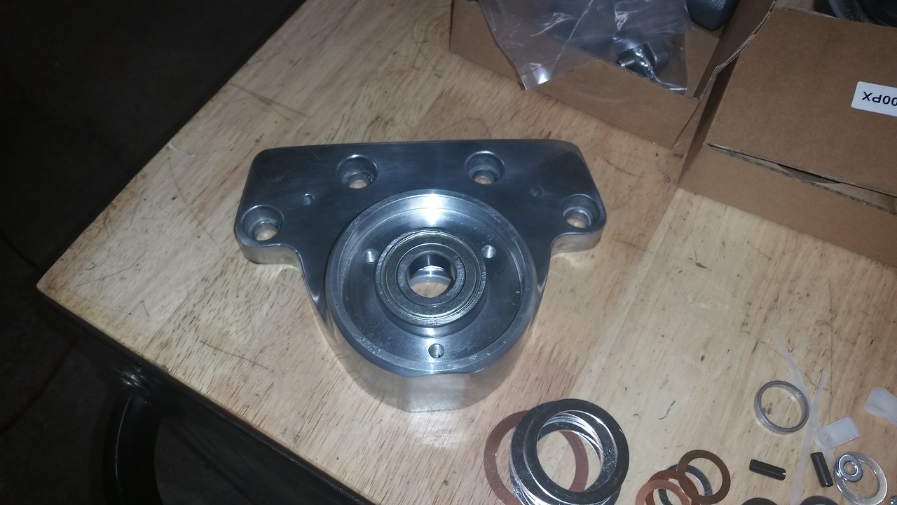
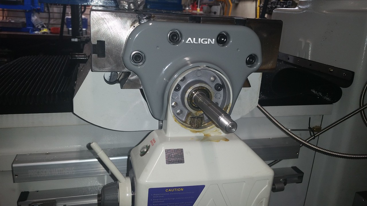
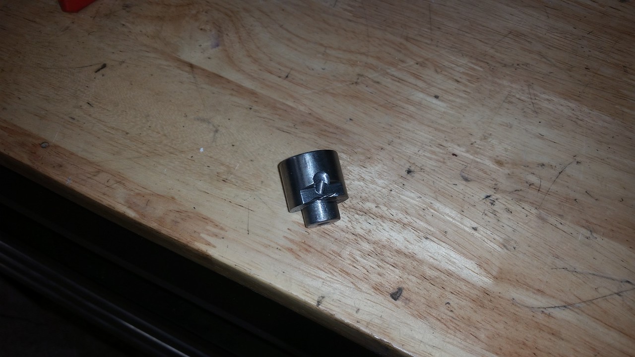
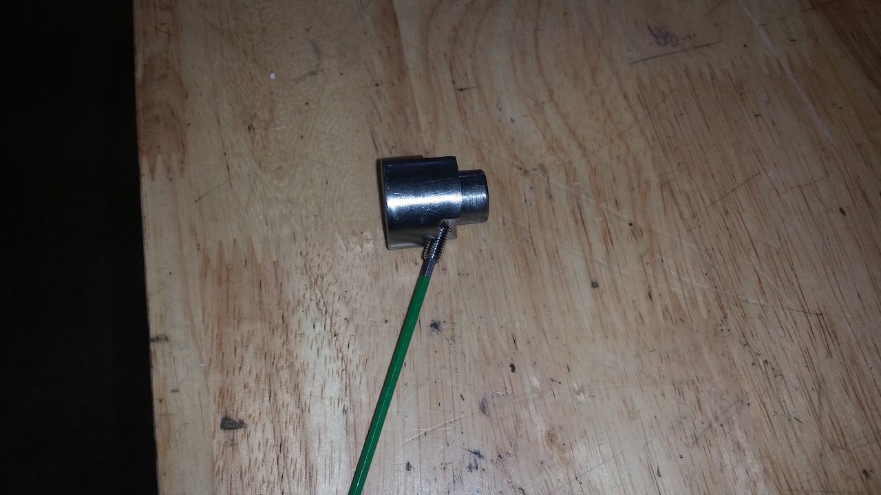
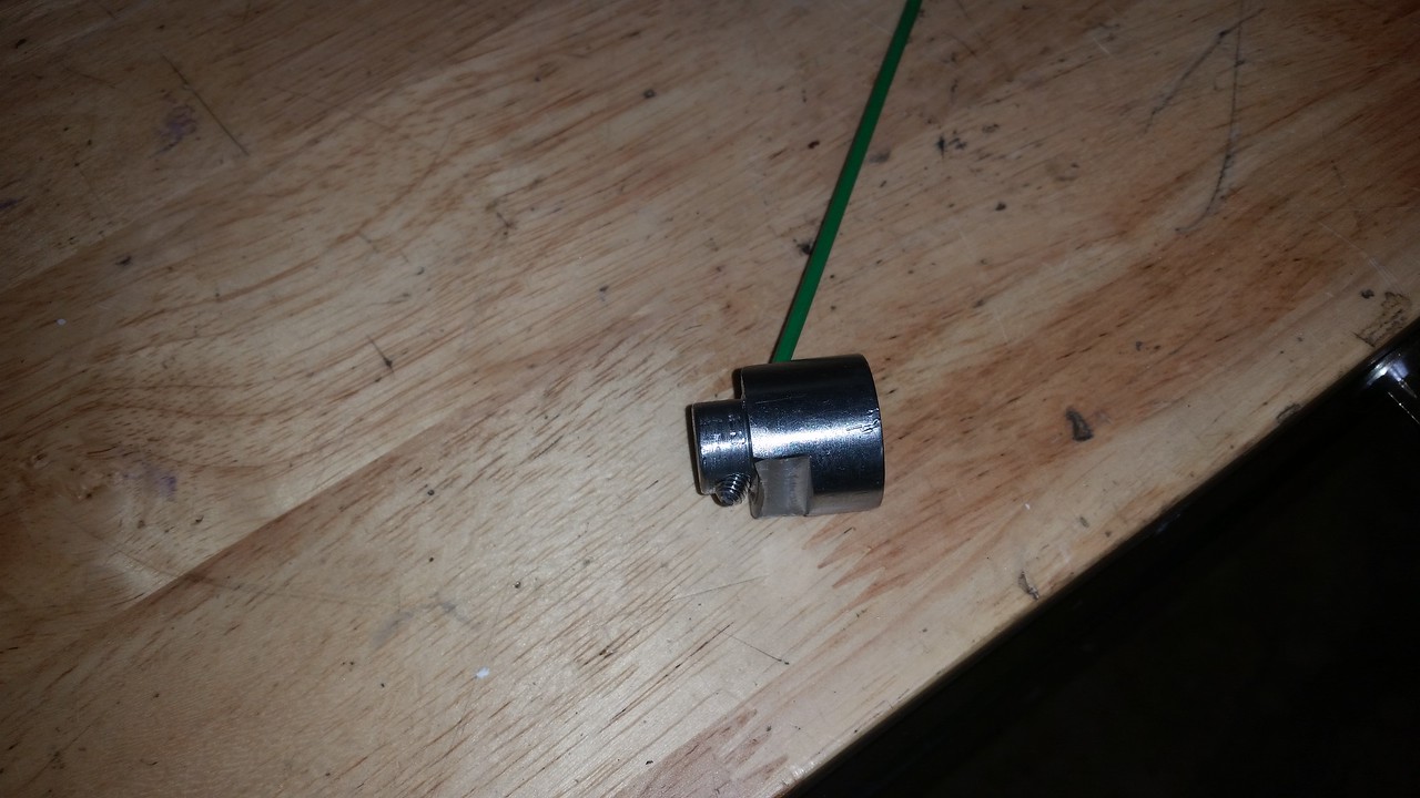
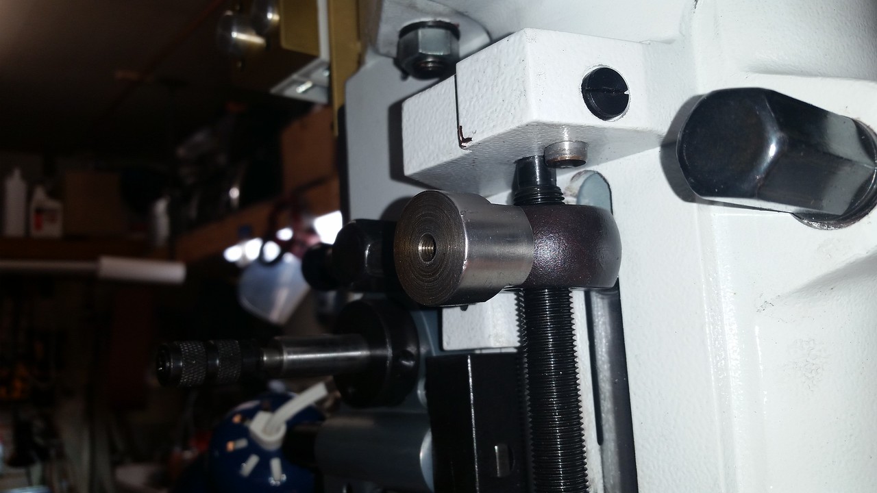
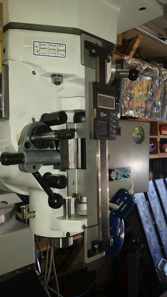
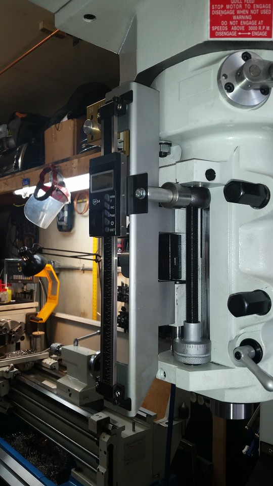
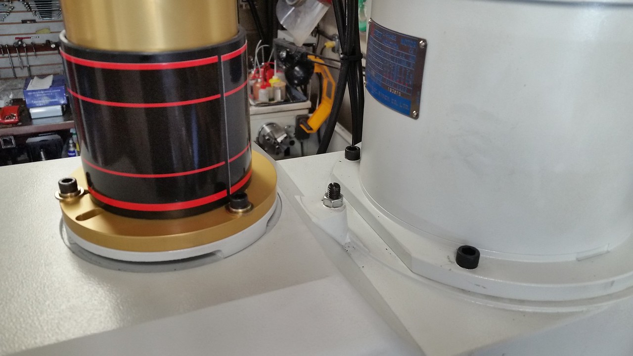
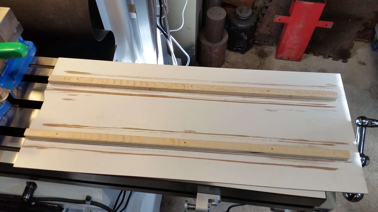
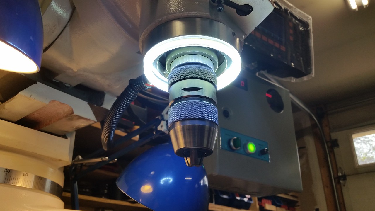
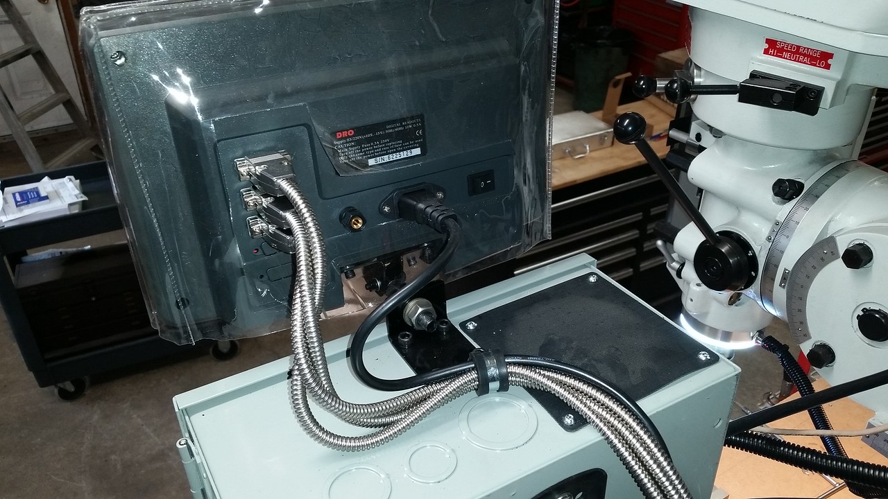
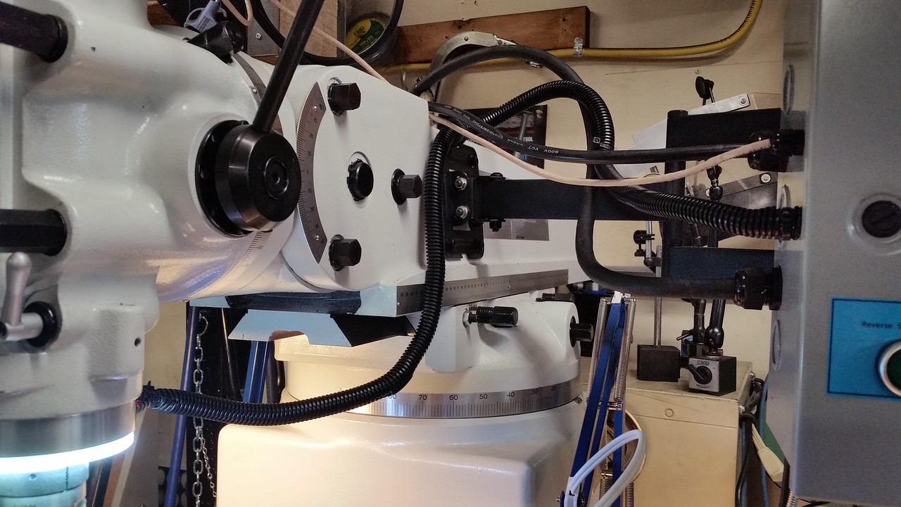
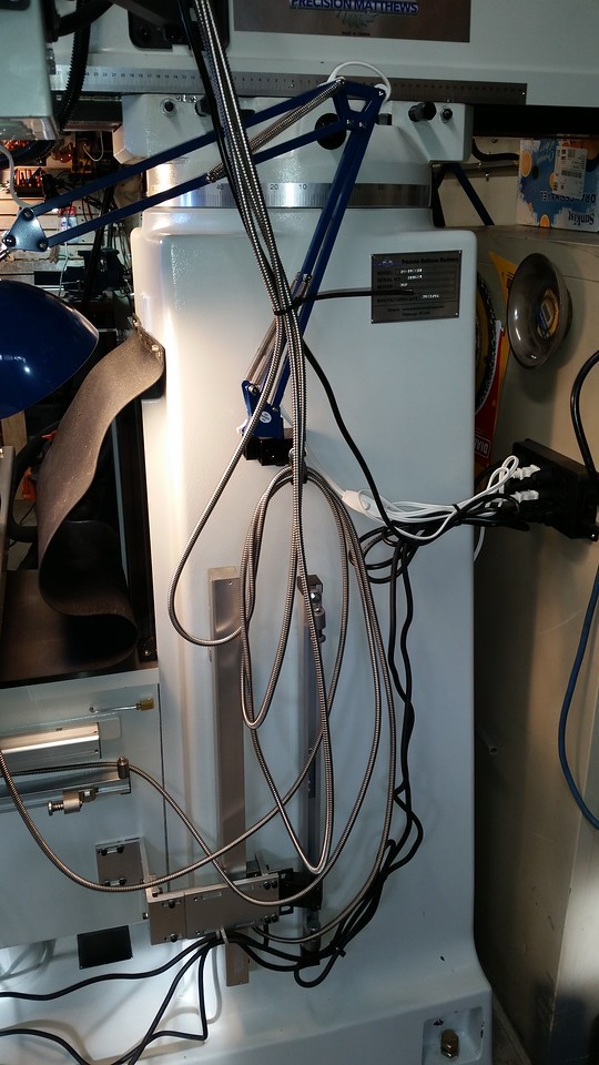
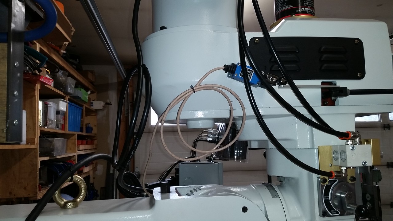
The next morning I decided that installing the Z axis DRO scale would involve moving the knee full travel bottom to top at least a few times to measure scale alignment. After I did it once I decided to put a hold on the DRO install while I installed the Z axis power feed. It takes 90 rotations of the knee lift crank to go full travel and my shoulder was complaining after half travel. The power feed install threw a curve at me when the extension shaft would not engage the threads on the original shaft. After a bit of head scatching I realized the original shaft was too long and after careful measurements I cut off .600" to make it fit. It went smoothly from that point. I only needed one .010" shim to get the gear mesh set correctly.


Beautiful mill!!
Out of curiosity, I see you suspended the mill from the eyelet in the ram.
I believe that is for removing or suspending the ram for service.

PM may be different than other vertical mills.
I heard that from other people before I did it but was assured by the guys at PM that it OK. This is a page from the user manual.
 

Attachments

  • mill lifting.png
    mill lifting.png
    116.3 KB · Views: 68
After the power feed install I got serious about the Z axis DRO scale. What make this one a challenge is making the scale align perfectly with the knee travel when the column of the mill is tapered top to bottom and front to back. After some measuring trial and error I decided I could deal with the 2 degree angle front to back using an angle block in the milling vise so I went ahead and made the first chips. I dealt with the taper from top to bottom with different height mounting blocks with narrow 5mm wide contact pads to prevent introducing bends into the mounting bracket. I learned a lot during this exercise, I just hope I can remember it next time I have to deal with a mounting challenge like this. I finished the mounting brackets for the read head next. Matt sent me some pictures showing how they set up the brackets when they install the DRO and I had to make some custom parts.


Over the next couple of days I got the X and Y power feed units and the power draw bar installed. I'm glad I ordered the power draw bar, even when standing on a 2 step stool I can't see the draw bar, I have to loosen by feel. This Torque-Rite unit is pricey but comes enough hardware to mount it on pretty much every possible Bridgeport or clone you could find. Absolutely every thing I needed came in the box except Teflon tape. It even came with a bottle of air tool oil.

I spent extra time getting the backlash in the power feed drive gears as low as possible while still having some, these unit came with a selection of shims down to .003" thick so it was possible to really dial the backlash down to a low amount. These are the quietest ones I have ever seen, really happy I spent a few extra buck and ordered the Align brand units. I still have to do some work on cable management as it looks like a den of snakes right now and I still have to install the quill DRO. I'm working on the tachometer speed sensor and magnet mounting but the machine is pretty much ready to go to work. I trammed the head this morning and got it dialed in at less then .0005" deviation on both axes. I need to get some sort of table covers as well, I have already made a couple of marks on that shiny new table. LoL

I also fabbed a couple of mount for my Ikea work lamps. You can't go wrong for $15 each for these things, they even had blue ones to match the blue on the new mill!


I installed the quill DRO that was on my old mill. I made a new plug to fit the quill stop. It has M5 female threads so it can be attached to the sliding part of the scale. It drilled and tapped a through hole in it at a 45 degree angle for an M5 set screw to retain it in the quill stop. I had to drill 1 new mounting hole in my bracket as the original screw hole did not line up with the hole in the new mill.


I've had the feeling that the spindle speeds were not as high as indicated on the front panel dial so I used my hand held tach and sure enough 4200 rpm indicated was 3400 rpm actual. Looking at the motor sheave pulley the belt should be right to the outside diameter at the highest speed but it was about a half inch inside that. I had to turn the adjuster for the front sheave rocker arm a full 3 turns to get it so the belt goes within about .060" of the OD of the motor pulley and gives me 4060 rpm max. I could get 4200 but I prefer to keep the belt a little inside the max diameter of the pulley. I tried to get a pic of the belt position on the motor pulley but it's just too dark and hard to see in there for the camera. The rocker arm adjuster screw is on top of the head between the motor and spindle. I picked up some 1/8" hardboard at Lowes and made up a pair of table covers that fit into the T slots and lift out of the way easily.


The last bit of work on the Teco L510 VFD was installing a brake switch. With this switch input to S4 of the VFD it will enter "base block" mode as Teco calls it. This mode allows the spindle to coast to a stop so the mechanical brake can stop it as fast as I want and will not conflict with the normal deceleration times.


A thing of beauty! Congratulations!
Love that ER40 Collet Set, may get me one soon!
Took me a solid week, working relentlessly to get my PM-935TS setup with all her accessories, they are wonderful machines!
I opted to mount mine a spreader base Made from 2"x4" Steel channel
View attachment 381610

You'll probably need to make a spacer like this also, from 0.060" aluminum sheet stock to space the X-axis power feed when mounting.
View attachment 381611
Thanks, I watched the Clough42 video where he talked about the issue with the inner bearing race and spacer. On this machine the inner race is a tight interference fit over the lead screw so I drove it onto the screw with a brass punch so it is centered inside the bearing and I didn't need to make the shim or use the bearing spacer. I have been watching your thread on your new PM mill with great interest.
 
I machined the parts to install a digital spindle tach, the design was copied from one made by David Best on this forum. The collar is cast iron and is a slight interference fit onto the spindle, just a little heat with a heat gun and it slides on but it also has a back up brass set screw holding it. The magnet is attached to the collar with JB Weld the same as I did on my lathe. The sensor ring is aluminum and is a slight interference fit over the nose cap on the quill but also has a stainless M5 set screw holding it in place. The light ring is a 100mm LED halo light from Amazon and is held to the sensor ring with 2 sided tape. I drilled and tapped the sensor ring M12 X 1 so the sensor screws into it and has a jam nut to keep it from moving. There was no plug/wire harness with this tach so I soldered the wires directly to the pins on the back of the display. The harness with the tach sensor and light ring wires runs straight out the back of the sensor ring and I covered it with 1/2" split loom for protection.


I'm almost embarrassed to show the inside of my VFD enclosure as it looks pretty primitive compared to a Mark Jacobs or Cletus job but we do what we can with the skill we have.


I also did a little cable management, more to come.


Back
Top