- Joined
- Jan 25, 2015
- Messages
- 2,558
So yeah, it's been tried before. We all know the results are marginal at best. But I've got a bunch of junk taking up space and a mill (even limited) would be useful from time to time. I do have an original Atlas milling attachment and it works well for very small items, but the travel is very limited on that and sometimes i could use a few more inches of travel to finish a piece, rather than repositioning and rejigging everything. There's also times when the vertical milling attachement just isn't capable of holding certain items or capable of getting hte work piece in the right postion, where a horizontal t plate would work much better.
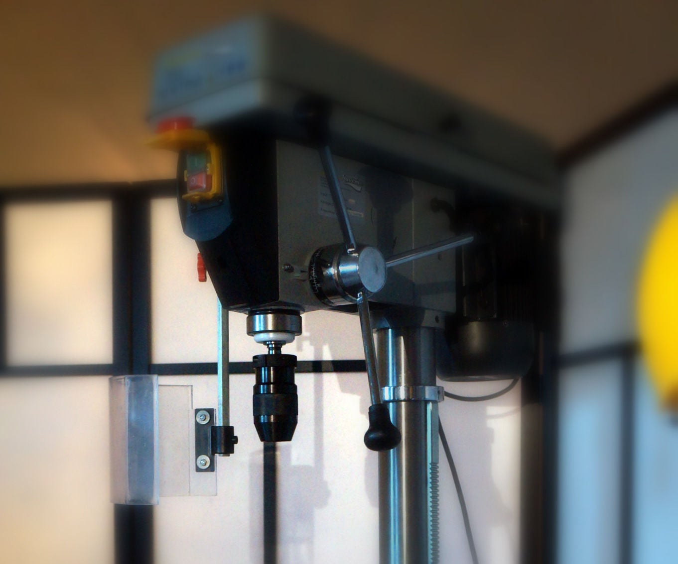
First is the base material, a generic 8" drill press. You know the type, Chinese, mass produced, not exactly all that capable, even as a drill press. So I strip it down and check the runout on the quill. It's got a JT33 chuck, but that's going away. So I checked the quill on the jt33 taper once the chuck was removed.
At first blush, it's didn't look too bad. Only about a thou runout. But then I tried pressing on the quill (while extended fully) and the issue with these cheap little things became obvious: about .005 play. Bearings are actually very tight (with movement so little it doesn't even really measure) and further investigation revealed it's the clearance between the quill and the bore it sits in. Five thou is actually workable for the small projects I need it for, but I have a few ideas on how to take up that slack. I'll definitely have to look and see if I can get that runout down as it will only be magnified by any play or flex in other parts of the machine.
I could just use the drill chuck to hold end mills, but I wanted a little more accuracy than that. So I found an er32 spring collet holder with a JT33 taper to fit on the drill press quill. Again, not the the most rigid or accurate setup, but its still better than just a cheap little chuck.
Next I needed a way to feed the quill down to the work without having to fight the return spring. I could just remove the spring, but then I'd have to be cautious of the quill coming loose and dropping into the work piece. So the spring stays and I'm going to build a worm gear arrangement to give me the up and down feed.
For rpm, I'm going to install a little digital readout for the chuck speed and for now, speeds will be changed via the stock belt and pulley drill press setup.
I'll need a quill lock. but that's a simple job of drilling a hole and installing a threaded bolt for a lock.
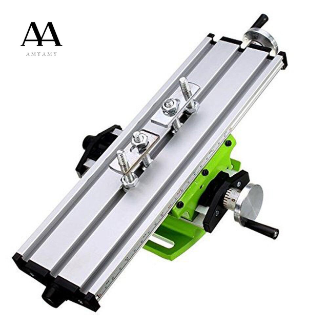
Most guys use an xy table when doing this sort of thing. That's more money and I'd like to make this as "frugal" a build as possible. So the plan is to mount the drill press behind the Atlas TH42 (towards opposite end from the head-stock)and use the cross slide as the xy table. I'm already making a t slot plate for my milling attachment and it already mounts to the same tapered boss on the milling attachment as the compound rest, so it will drop right on to the cross slide as is. the benefit of using the lathe slide is it will give me much more travel as opposed to the limited travel of the milling attachment as well as any generic xy table.
I can already hear the flex, movement and accuracy comments about mounting a drill press behind the lathe and using the lathe slide. here's the thing: my lathe is mounted on a table with 1/4" plate as the top and 2x4 tube is welded to the underside directly under the lathe ways. what I'm planing to do is weld another section of 2x4 tube under the table where the drill press will be bolted to. Essentially, the new piece of tube will be at a right angle to the existing one and welded to both the long tube and the table top itself.
The drill press itself will be be shortened as much as possible in order to try and eliminate as much flex as possible.
So far, I've got about 50 bucks Canadian in this, not counting the drill press, lathe and other bits I already had lying around.
Yes, it' going to be pretty limited, but this is as much about seeing what I can build out of some "scraps" as much as actually using it. And as mentioned, my needs (and expectations) are pretty minimal, so it's worth a try to build something.
Pictures to come as I start building it.
First is the base material, a generic 8" drill press. You know the type, Chinese, mass produced, not exactly all that capable, even as a drill press. So I strip it down and check the runout on the quill. It's got a JT33 chuck, but that's going away. So I checked the quill on the jt33 taper once the chuck was removed.
At first blush, it's didn't look too bad. Only about a thou runout. But then I tried pressing on the quill (while extended fully) and the issue with these cheap little things became obvious: about .005 play. Bearings are actually very tight (with movement so little it doesn't even really measure) and further investigation revealed it's the clearance between the quill and the bore it sits in. Five thou is actually workable for the small projects I need it for, but I have a few ideas on how to take up that slack. I'll definitely have to look and see if I can get that runout down as it will only be magnified by any play or flex in other parts of the machine.
I could just use the drill chuck to hold end mills, but I wanted a little more accuracy than that. So I found an er32 spring collet holder with a JT33 taper to fit on the drill press quill. Again, not the the most rigid or accurate setup, but its still better than just a cheap little chuck.
Next I needed a way to feed the quill down to the work without having to fight the return spring. I could just remove the spring, but then I'd have to be cautious of the quill coming loose and dropping into the work piece. So the spring stays and I'm going to build a worm gear arrangement to give me the up and down feed.
For rpm, I'm going to install a little digital readout for the chuck speed and for now, speeds will be changed via the stock belt and pulley drill press setup.
I'll need a quill lock. but that's a simple job of drilling a hole and installing a threaded bolt for a lock.
Most guys use an xy table when doing this sort of thing. That's more money and I'd like to make this as "frugal" a build as possible. So the plan is to mount the drill press behind the Atlas TH42 (towards opposite end from the head-stock)and use the cross slide as the xy table. I'm already making a t slot plate for my milling attachment and it already mounts to the same tapered boss on the milling attachment as the compound rest, so it will drop right on to the cross slide as is. the benefit of using the lathe slide is it will give me much more travel as opposed to the limited travel of the milling attachment as well as any generic xy table.
I can already hear the flex, movement and accuracy comments about mounting a drill press behind the lathe and using the lathe slide. here's the thing: my lathe is mounted on a table with 1/4" plate as the top and 2x4 tube is welded to the underside directly under the lathe ways. what I'm planing to do is weld another section of 2x4 tube under the table where the drill press will be bolted to. Essentially, the new piece of tube will be at a right angle to the existing one and welded to both the long tube and the table top itself.
The drill press itself will be be shortened as much as possible in order to try and eliminate as much flex as possible.
So far, I've got about 50 bucks Canadian in this, not counting the drill press, lathe and other bits I already had lying around.
Yes, it' going to be pretty limited, but this is as much about seeing what I can build out of some "scraps" as much as actually using it. And as mentioned, my needs (and expectations) are pretty minimal, so it's worth a try to build something.
Pictures to come as I start building it.
Last edited: