1440TL VFD Conversion

bdstark

H-M Supporter - Sustaining Member
H-M Platinum Supporter
Joined
Dec 10, 2023
Messages
4
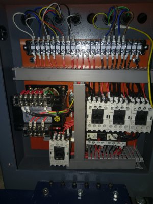
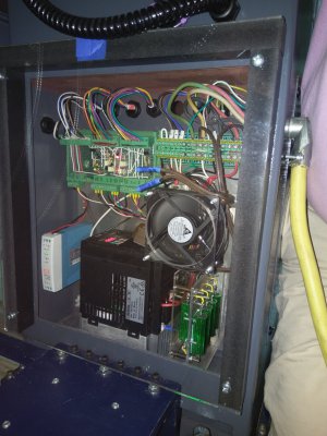
Converting a new 1440TL to VFD (Hitachi WJ200-075LF) and was considering replacing the entire electric enclosure with one that would fit the VFD. The current panel measures ~24"H x ~20"W x ~5.75"D, with the VFD ~10.25"H x ~5.5"W x 6.25"D, so there is no way to fit it in. Since the conversion replaces the contractors and most of the wiring will be replaced, removing the current enclosure and putting a ~30"H x ~20"W x ~10"D would provide enough space to mount the VFD, new relays, etc...

That size enclosure in steel is ~$400, fairly expensive for what it is - getting halfway through and realizing it won't work would be painful. Does anyone have any experience doing an enclosure swap like this? Any reason this would be a bad idea? I've bee trying to find what enclosure size does't require a fan and vent with no luck, but I have found plenty of notes that smaller enclosures don't so I assume it would be fine; I can always add a fan in the future if needed. The lathe is not against a wall, and there isn't a good place to place a second enclosure, either freestanding or on the machine.

The new enclosure would stick up about 6 inches higher than the current one, which is flush with the gearbox. The extra space provides a location to potentially mount a tachometer on the backside, facing the front. I am fine if it just sticks up a bit regardless. I could get an enclosure the same height (or close) and just deeper for the VFD to mount if there is enough room otherwise; the current panel is fairly full and being my first conversion, a little extra space would make it easier.

If replacing the enclosure is a bad idea, where have others mounted the VFD and any extra items in a standalone lathe? I looked at the space under the gearbox with the motor, but eliminated it as too cramped (and a bit of a hack).

Thanks

Brian
 
I use a separate enclosure for my 1236T and mill. I have that on a wooden stand behind my mill. I put both VFDs in that enclosure as well as the circuit breakers and have a smaller one at the lathe for the relays. The mill just has a pendant with the controls in, so it doesn’t have a separate controls enclosure. You can use the existing lathe enclosure for your control relays, and then get a smaller one for the VFD and mount anywhere convenient.

With a metal enclosure, you can get away without a cooling fan in many cases, the enclosure itself acts as a heat sink to the environment. These machines are usually used intermittently, so don’t generate enough heat that they would overheat unless your ambient gets hot. If you go with plastic, you won’t have that same heat transfer and probably would want a cooling fan in there. This document will help you calculate your heat load to see if a fan is necessary and shows options.

 
There are several approaches to this.
1. Have a big passive heatsink on the outside at the back.
This is still expensive, and does require safe insulated heat conduction path from inside to outside. I used this way for Triac 3-phase variable PID control of a 12kW furnace. The external heatsink was about 12" x 12" x 4" fins, and you could touch it, note that it was hot, but not too uncomfortable. I get it that you are talking of a 2 or 3kW VFD, but I mention it only for context, to get perspective about what is reasonable. The enclosure was about the same size as yours, because there had to be all sorts of contactors, and E-stop controls, and PID instruments on it.

2. Have it all inside one enclosure, without fans.
For this way, provided the whole box has enough area to radiate away the heat without itself becoming unreasonably hot, and internally, the bits getting lots hotter don't challenge the specs of the VFD, you can do this, with the advantage that the whole box is sealed, and won't let in conductive carbon dust, shards, and deposited greasy films, without need for filtering. It can work, with a big enough box, but I never trusted it.

You can discover the °C/Watt dissipation constant of the enclosure buy temporarily rigging up some kind of heater inside it, along with a temperature probe or thermometer, whatever, and letting the inside temperature stabilize. The box is otherwise empty. You don't even need the real box, a lashed up similar sized substitute, stuck together with duct tape will do. I once used a 500W heater, but some light bulbs, whatever will do, just so long as you know the voltage, and the current, you get to the Watts. It does not have to be the same wattage as the VFD. Anything will do.

From [T_inside - T_outside] / Watts gets you the °C/Watt constant for the box. Now you can get to how hot it will end up inside. VFDs can be quite efficient, so check the spec on how much it will dissipate inside, when delivering full power worst case to your loaded machine. Many (most?) VFDs have a fitted heatsink fan. This will circulate and move the heat about to the inside of the box.

Now you can figure out if it will work! Choose a temperature for a reasonable day outside the box. It might be 25C (77F), or your shop might get hotter. Pick the worst case if you like.
Add on how much hotter will be the inside of the box.
Get to the VFD spec, and check out it's "get hot" dissipation constant. Now you know how hot it will get above the temperature inside the box. If it does not look uncomfortable, stay with it. I am a bit conservative about it. I would not want the VFD heatsink to get above (say) 65C, which is a bit too hot to touch, but not outrageous.

3. You can fan-cool the box. This is the way I trust, second only to huge exterior passive heatsinks. It does rely on the fan(s) never failing. Your VFD might have provision for an external power resistor to provide the dissipation for motor braking and speed control. It usually has to handle only some fraction, like 10% of the full power, during transients, a few seconds at a time, but it might get hot. Without it, VFDs have to handle the (high) voltages generated on overrun. If the VFD has provision to connect one, then do use it. Some VFDs might have one on their own heatsink.

ALWAYS fit filters at the inlet and exit. I choose inlet at the bottom, and exit at the top, and arrange to aim cool air right into the VFD. If the VFD has it's own fan, then sensibly, it should suck in the right direction to just take up the incoming air. If it does not, then you may have to move the inlet fan to the top. This way, the box can be just about as small as you can get, and still fit around all the stuff you put in it. It goes without saying not to mount inlet and exit fans on the same end of the box. On the sides at opposite ends is OK.

Putting at least some kind of filter on the air exit is to keep shop airborne sticky dusty junk from building up on the electronics, from the times when it is switched off. For me, the extremes was 2 x 70kW servos, with input filters and power factor correction, etc. One was to control incoming, and the other to return power to the grid. I used two 1.8m rack cabinets, and I kept down the fan roar by going for larger diameter (250mm), slower running fans, two per cabinet.
---
From my own sense of proportions here, I would say your cabinet is generously enough in the main dimensions, but perhaps you might get a little cramped in the depth. Fitting a backplate to take DIN rail and suchlike, to mount the VFD, and the various other stuff you might need, takes up some of your 5.7", and then stuff you might mount on the door might need clearance over stuff inside unless you are careful about placement. If it is a no-frill box, and has fan cooling through, then go as close as you like.

Another general wisdom is do not rely on the VFD fan to do all the cooling. Its job is to move the heat onto the heatsink, and into the environment temperature inside the box. It is up to you to make that inside box temperature get closer to the outside ambient.
 
Last edited:
Hi Brian,

I'm in a similar boat with a 1640TL and Yaskawa GA500 VFD (which is almost 7" deep). My choice was to go with a 24x20x8 cabinet because there's just not a real clean way to stick a separate box on the back of the lathe (opinion). I've got some angle steel I'm going to build a small open-top frame with and sheet the sides and bottom, with a removable panel on the "front" - the side where the cabinet door is. This little frame will bolt where the existing cabinet rests on an L-bracket, allowing me to run the cables out the bottom of the cabinet into the frame and off to where they need to go on the lathe. Otherwise since the existing cabinet has the wiring exiting the back of the cabinet I'd have to cut the subpanel a bit for clearing the glands and such. I believe the new 24x20x8 cabinet is just a hair shorter than the existing one for whatever reason (half an inch or so?) and a hair narrower as well, and I decided not to stick a piece of lumber on top of the bracket to make up that difference to keep the top flush.

My suggestion would be to figure out what all you're going to need in your cabinet, then use a scale model of the subpanel (paper cutouts, CAD, whatever) to arrange all the things and see how it all fits. You may be able to get by with the 24x20 size instead of the 30x20. To take the pressure off, figure out what size you need before you spend the money instead of being forced to cram stuff in there or have a bunch of extra space. My cabinet design is pretty sparse with all of the contactors and transformer removed, a 30" tall cabinet is definitely not warranted in my case. It would be downright ridiculously empty if I put the VFD and power related components in a separate enclosure, but YMMV depending on how you design your panel.

I am not a control panel expert, I may have the entirely wrong idea. I do have a thread here begging for information and developing a plan, perhaps so others can see what not to do. But that's my free advice and it's worth every penny. :)

-Doug
 
Does anyone have any experience doing an enclosure swap like this? Any reason this would be a bad idea? I've bee trying to find what enclosure size does't require a fan and vent with no luck, but I have found plenty of notes that smaller enc

I'm in a similar boat with a 1640TL and Yaskawa GA500 VFD (which is almost 7" deep).

I will be happy to try to help you guys out with this. I agree, why use relays when you are putting in a solid state VFD that provides all of the functions. I converted my PM1440GT. The TL is bigger machine, but other wise very similar with the same concepts. See my posting. I am currently working on a pcb (I have it in hand, just have not tested in the lathe yet.) to replace the hand wiring that I did. You would be welcome to the design or even a board. In fact, I have alternative designs which are simple to do. If you have not already see it, download the Part 2 attachment for a detailed description. With the transistor conversion I got rid of all of the big relays and the big transformer, which made lots of room in the existing enclosure in the back of the stand. I did put in one SS relay to control the coolant pump, but it is way over kill. Anyway, there are some pictures on my posting.
VFD conversion using solid state electronic components.

I did not have to do it, but I extended the enclosure in the stand by an inch so as to allow a natural vertical air flow. Made it from plexiglass so I could look in and see the the VFD display and my ckt board LEDs. I put a small fan on the plexiglass, but don't really think it was needed and it sort of screwed up the appearance! By the way, included a home made e-braking resistor right in side the enclosure. Tested it and it does not get more than a little warm.

Dave L.
 
entire electric enclosure with one that would fit the VFD. The current panel measures ~24"H x ~20"W x ~5.75"D, with the VFD ~10.25"H x ~5.5"W x 6.25"D, so there is no way to fit it in.
The main purpose of mounting these with the head sink to the back of the enclosure is to trap the air flow through the heat sink. If you rotate the VFD so that the 5.5" becomes the depth will it not fit? Then orient the display so that it is up. I mounted mine on a plate at the heat sink to trap the air flow inside the heat sink. With the display upward I could look down at my VFD display which is in the stand below the lathe. (You never look at any of this stuff after it is installed and working.) You can do this and then mounted the plate via its thick edge to the directly to the back of the enclosure, if you have access to the back side, or via a 1/8 sheet of Al. The internal fan will keep it cool and plate attached to the heat sink will carry extra heat to the enclosure surface. use Al for the plate as it is a better heat conductor than steel.

Dave L.
 
I think you have the right idea to replace the enclosure. The size you are considering seems large to me. If you have a solid idea of what will end up in the panel, it would be worthwhile to sketch the layout with devices and terminal strips before investing $$. With that said, working in an oversized panel is much more pleasant than working in a panel that is stuffed full. One option is to mount some of the small devices to the door to save space.
 
I used to put the enclosure on the back of the machine but if the lathe will sit near a wall, I prefer to attach it there and use pin connectors or a small terminal box to attach to the machine. I like to see the VFD display and it helps me to remember to turn off the main switch. If I can't find a reasonably priced enclosure with a window, I cut one it with a cheap plexiglass kit. Dave
 
what will end up in the panel, it would be worthwhile to sketch the layout with devices and terminal strips

That is basically what I did only I did the layout of the components on the plate that bolts into the enclosure. I wanted to keep everything in original stand enclosure of the lathe. PM1440GT. So if you lay everything out on the mounting plate then you can use this same drawing to locate any bolt holes etc and drill and tap from it.

1) Attached shows a photo of the enclosure with the original relays. transformer, connectors, etc. Everything in here was removed as one unit and put in storage. The backing plate was made out of some sort of stiff orange polymer. A row of feed through holes along the top for both the control wires (left) and the power wires (right). The machine was never hooked up to 3 phase power so the terminals on the far right top are empty.

2) Attached shows a photo of the enclosure with the new electronics built on a backing plate (Al) that come out of the enclosure in its entirety. The after thought fan is mounted on the transparent cover and is both ugly and over kill.

3) Figure 4 (pdf) shows the backing plate sketch with the layout placement of the new components. Control electronics board at the top left, the heavy duty connections at the top right, bottom center shows the VFD, the bottom right is the braking resistor, center left side shows the 24 V dc power supply used for the electronics and the lathe light etc. The middle right device is the solid state relay used to switch the 220 coolant motor (over kill at 30Amps, but I had it laying around). Next to this is a small mount for a fuse holder that I also had laying around. The coolant motor is fuse at ~0.3 amps.

4) Figure 5 (pdf) shows sketch with the dimensions of the lathe stand enclosure with the holes and the mounting plate located in it. Note the enclosure opening hole is smaller than the inside of the enclosure. Note also the 4 gray enclosure tapped mounting holes and the wire feed through holes, at the top, are all original. So the backing plate with components mounted were designed to go through this hole.

What you may observe from this is that there is actually space left over.

I think these figures were in my VFD write up posting.
 

Attachments

  • IMAG2252.jpg
    IMAG2252.jpg
    305.8 KB · Views: 28
  • 08a IMAG3313 Rear Final IMAG3313.jpg
    08a IMAG3313 Rear Final IMAG3313.jpg
    318.7 KB · Views: 31
  • Figure 4 PM 1440GT VFDDescript Part 2 DNL L905_1732.pdf
    208.6 KB · Views: 21
  • Figure 5 PM 1440GT VFDDescript Part 2 DNL L905_1732.pdf
    100.4 KB · Views: 20
I used to put the enclosure on the back of the machine but if the lathe will sit near a wall, I prefer to attach it there and use pin connectors or a small terminal box to attach to the machine. I like to see the VFD display and it helps me to remember to turn off the main switch. If I can't find a reasonably priced enclosure with a window, I cut one it with a cheap plexiglass kit. Dave
Yes, access can be a problem for some folks. I used the plexiglass cover so that I could lean behind the machine and see the VFD display and the LEDs that I put on my electronics. However, never have to. (I also thought about putting a mirror against the wall to refect the view.) I have my power switch mounted on the wall. The lights and displays on my control panel at the front of the lathe make it very clear as to whether or not the machine has power! WRT to getting to the electronics ,which I never have needed to do, I left sufficent room (shoulder width) to just squeeze in to remove a component, but I also put the lathe on casters so that I can simply raise the leveling bolts so that the lathe rests on the casters and then I wheel it out. But I have never had to do this. One of these days I will get into the back to change out the electronics board with the pcb I have had made. (You can see the hand wiring of my original board in the second photo.)

Dave L.
 
Back
Top