1440TL VFD Conversion

Yes, that looks very nice. I hate leveling ( setting ) a lathe so hopefully mine won't be moved until I die. My big Monarch with 8 points and 8000 lbs is so rigid that the adjustment process takes weeks. Dave
 
This is a reasonably priced ($177) enclosure of adequate size (20x24x8) and it is 304 SS Nema 4. Volume and using a metal enclosure is sufficient to not need a cooling fan for this size VFD/enclosure. I prefer to mount a tach and speed pot in a separated box that I mount with an L bracket below the DRO, there are different options, this should not dictate the enclosure size. I have used Vevor enclosures for some of my builds, they are decent, although the back plates on some models are a bit thin. The back plate is galvanized unpainted metal which is uptimal as a ground plane. By mounting the VFD to the back plate it will stiffen it as well if you can mount the braking resistor if there is space. On some installs I use either a narrow long braking resistor, some installs a thin wide ones that is mounted on the backside of the back plate. VFD's are suppose to be mounted vertically per the manufacturer this has to do with both cooling as well as the capacitor mounting position. You need to allow at least 3-4" of space above and below the VFD for airflow. The VFD fan can be set in several modes, I usually set mine to only come on when the VFD is in a run command, there is also a cool down cycle that it will run for several minutes afterwards. I see no reason to have a viewing window for the VFD enclosure, but once can always add a viewing window to a solid door if one desires.
 
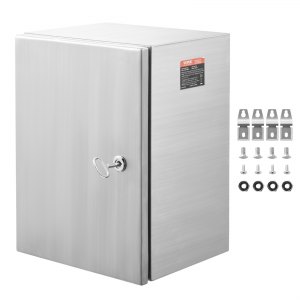
Thanks for the input - I went ahead and ordered a 24x20x8, the Saginaw SCE-24EL2008LPLG with the galvanized subpanel SCE-24P20GALV from Automation Direct. An 8" enclosure will line up with the lathe and look better than the 10" would have. A 30" enclosure would have been silly once I laid out the components. After it was delivered yesterday, I was sweating a bit looking at it and the VFD depth once the subpanel was mounted, but there was plenty of room. I saw the Vevor enclosure but at the time had it in my head that I needed the 10" deep enclosure, and when I decided to go with the 8" forgot about it. The Saginaw enclosure and subpanel feel solid and should be easy to mount to; hard to tell if it is $200 better though.

There are so many great threads about these conversions, most I have read a dozen times over the last few months. @mksj and @B2 (among others) deserve a special thanks for their many posts. I purchased a lathe and knee mill at the same time and am converting both, starting with the lathe. I like the simplicity of the solid state design - I read the thread, but had missed the attachment with the full right-up. I previously worked in broadcast engineering, and most (analog) equipment came with schematics and a "Theory of Operation" section that described how the device worked, and the write-up reminded me of those and how useful they were.

I would be very interested in a PCB, though I ordered the 4PDT relay which I think is all that is required for the VFD source design. The solid state design will be easier to upgrade in the future, though why an upgrade would be needed is unknown... I like the idea of using the DRO scales to trigger the lathe to stop, replacing or augmenting the proximity sensor. From my research, the PM scales use RS422 to interface with the DRO, and RS422 can be read by multiple devices simultaneously by tapping the Rx pair. It seems fairly simple to add a Arduino or Raspberry Pi, reading the scale, creating a pseudo-proximity sensor trigger. Without having used the proximity sensor, the scales seem like they would be more deterministic and repeatable, and eliminates the cables in the front.

The micrometer carriage stop has been backordered for a while, so the proximity sensor is missing a key component. I may have a go at the DRO scales as the trigger once I get the conversions completed. I ordered the DRO installed, primarily for the install, and intended to replace the head unit with a TouchDRO instance, at least on the mill. I've done a several applications with the Pi and linear/rotary encoders, and if a scale is similarly encoded a lot of the domain knowledge would transfer. (The rotary encoder state machine can be run via dtoverlay, eliminating missed steps, while the application runs in user space and can be preempted. My concern is slight delays periodically, but those delays would be milliseconds unless the operator did system updates while threading, a practice I would discourage.)

Thanks for the help - I'm sure I'll have more questions to come.
 
I would be very interested in a PCB, though I ordered the 4PDT relay which I think is all that is required for the VFD source design. The solid state design will be easier to upgrade in the future, though why an upgrade would be needed is unknown... I like the idea of using the DRO scales to trigger the lathe to stop, replacing or augmenting the proximity sensor. From my research, the PM scales use RS422 to interface with the DRO, and RS422 can be read by multiple devices simultaneously by tapping the Rx pair. It seems fairly simple to add a Arduino or Raspberry Pi, reading the scale, creating a pseudo-proximity sensor trigger. Without having used the proximity sensor, the scales seem like they would be more deterministic and repeatable, and eliminates the cables in the front.

It is nice to hear that you found the write-up, Part 2, attachement useful. It is amasing how many folks have down loaded this (267 as of today) and have never made a comment, good, bad or even a suggestion, about it. Even more folks have downloaded the Part 1 attachement which is a description of the way the system worked with relays when it arrived from the factory. Likewise, no comments!? I am sure there are all sorts of typos, misstatements, etc in these and if there was feed back I would correct them.

I am happy to help you with the pcb in anyway that I can,.... supply it, redesign it, purchase a new version. (I am not in this to make or loose money, just to help others.) My design included bells and whistles which some folks do not need. In most cases you just do not have to hook them up if you do not want to used them, but they cost virtually nothing. The biggest difference that might be for a different lathe or enclosure layout etc are the connectors as the wires may go to different places. By using just two cables to the front panel, I kept my compact and most of the wires then go to the front panel. But it is easy to change the connectors to fewer or separate them for different wire arrangements. Anyway, I have been helping a friend, @ptrotter, to do so and it has been worthwhile. He pointed out to me that not everyone needs a NO, (or a NC) proximity sensor so I made a small modification in the circuit for this. He prefered a NC so that if it is not connected the lathe would not run. It was trivial change to make.. .. I wanted the NO version so that I could have multiple proximity sensors. There is not really a safety issue for me as I still have the safety mechanical switch (NC) as well as the 1440GT has the lead screw clutch, which does work. One of the features of my circuits that is handy, is to have the volt meter that tells you the pot setting voltage before you engage the lathe. That way you know the approximate frequence the VFD is going to be running at before it starts up. The VFD does not show the output frequency until after you turn it on and the lathe is running. Most folks do not need the spindle revolution counter that I added. One other point, is that I found that be keeping everything close and in the original enclosure there were/are no noise problems/issues.

I agree with you that the proximity sensor function should be built into the DRO. I looked around a bit and did not find a source for this. I do not understand why this is not a standard feature as it is so easy to put into even a very inexpensive DRO! (I have never taken the cover off of the PM DRO that I had installed. Maybe there is a way to hack it?) I hate to do it external to the DRO a it is just more clutter around my lathe. So far by putting all of my controls in the front panel and keeping the DRO conversion in the original stand enclosure The only extra wires are due to the proximity sensor cable! I will look forward to hearing about something that you build in this regard.

Thanks for the feedback.

Dave L.

PS. The unpopulated pcb board cost about $25-30 for 5 of them. Most of this cost was the shipping! The manufacturer will even populate them for one and my guess is that it costs every little to do so. I just have not ask yet. I am sure that an smd version of components would only add a dollor or two to the cost. The most expensive items are probably the connectors.
 
Over the last week I started the panel build, which has gone well, and hopefully saying that doesn't jinx it going forward. The enclosure fit really well and was easy to work with. Since the enclosure is slightly smaller, I added a couple nuts between the existing bracket and the enclosure, making it perfectly flush at the top. Otherwise I matched up the existing holes, using a transfer punch when possible, and good luck when not. I didn't tap the subpanel holes, instead used rivet nuts which are just faster, though I countersunk them so they are flush.

Ordered the parts for the solid state build and should be getting it on a breadboard this week. I ordered from Mouser in bulk, so I have hundreds of spares of most components. I'll send a message about the PCB once I am ready to start that part, I'm hoping next week.

PXL_20240307_045435391.jpg


PXL_20240307_051025117.MP.jpg


PXL_20240307_045353628.jpg
PXL_20240307_051046707.MP.jpg
PXL_20240302_224806669~2.jpg
PXL_20240229_235005186.jpg
PXL_20240229_203432216.jpg
PXL_20240301_033853100.jpg
PXL_20240222_084125484.jpg


PXL_20240229_195320659.jpg
PXL_20240301_021211564.jpg
 
Hi @bdstark

Great! Pictures look impressive. I would love to have one of those magnetic drills!

Ordered the parts for the solid state build and should be getting it on a breadboard this week. I ordered from Mouser in bulk, so I have hundreds of spares of most components. I'll send a message about the PCB once I am ready to start that part, I'm hoping next week.

If you are following my circuit design. I can send you some design improvement if you want. @ptrotter and I have been discussing it and have actually gotten back some pcb boards. I have made a few improvements to my design. I also sketched out a couple which uses either a NC or NO proximity sensor. Just let me know and I will share. I did order a set of pcbs that is essentially the design that I posted. However, I just cannot seem to get around to populating it and testing it. You can have one of those if it will work for you and you can test it. Just message me with contact info.

You did not say what you are going to do with the front control panel? Do you plan to use the features that were in my posting? You could still use the board even if you did not include all of the features I put in my build.

VFD conversion using solid state electronic components.

Dave L.
 
Looks like the same brand of enclosure I used on my mill. Your work looks great. I did the same thing with the 240V input except that I ran a cord out of the enclosure and the socket is on the wall. I wanted a hard ground rather than relying on the ground through the neutral back through a secondary breaker box to the main breaker box. This is a short discussion on what I did on my mill. https://www.hobby-machinist.com/threads/electrical-box-for-mill-completed.110253/
 
Back
Top