1984 Crown Lathe (Honden) - Wiring Help Please

PancakeCritter

Registered
Registered
Joined
Apr 13, 2021
Messages
26
Hello,

First off, let me know if this is the wrong section for this, or maybe I should double post in the Asian Lathes section?

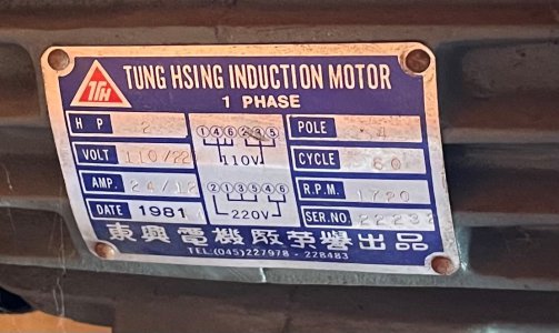
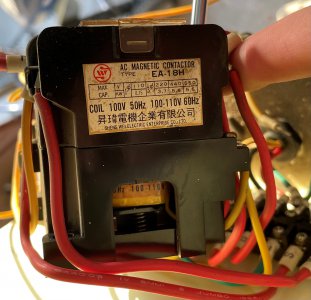
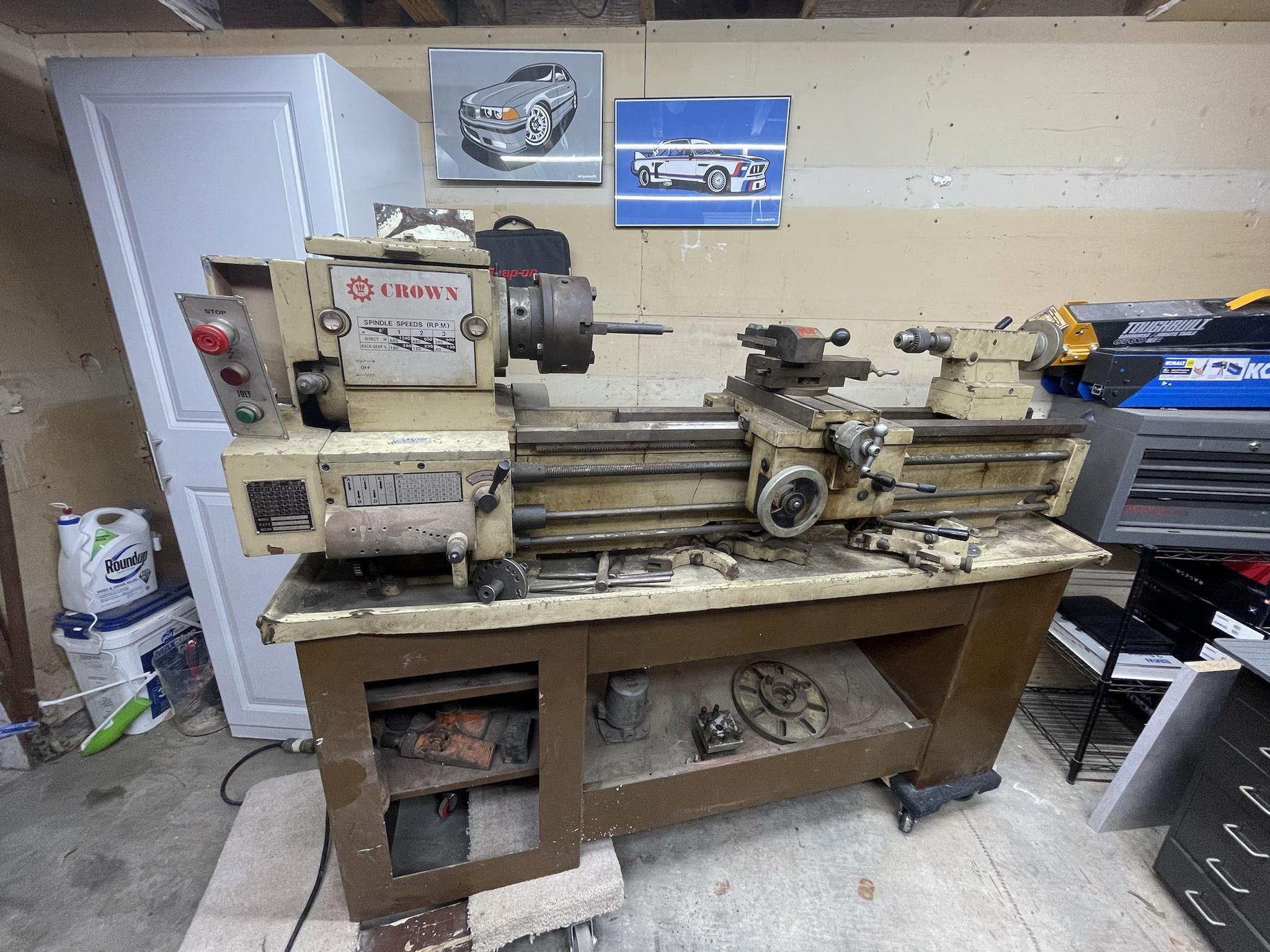
Anyways, I recently acquired a 1984 Crown lathe I am attempting to revive. It seems to be similar to the Honden/Jet lathes of this era. Unfortunately some of the wiring to the magnetic contactors isn’t complete. Would anyone with a similar lathe be willing to upload a picture of their wiring box?

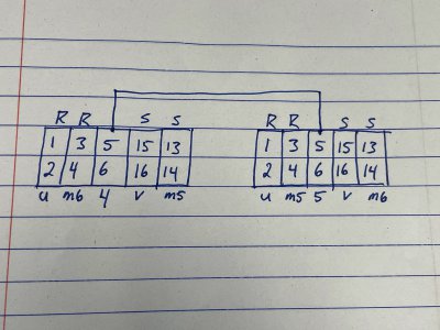
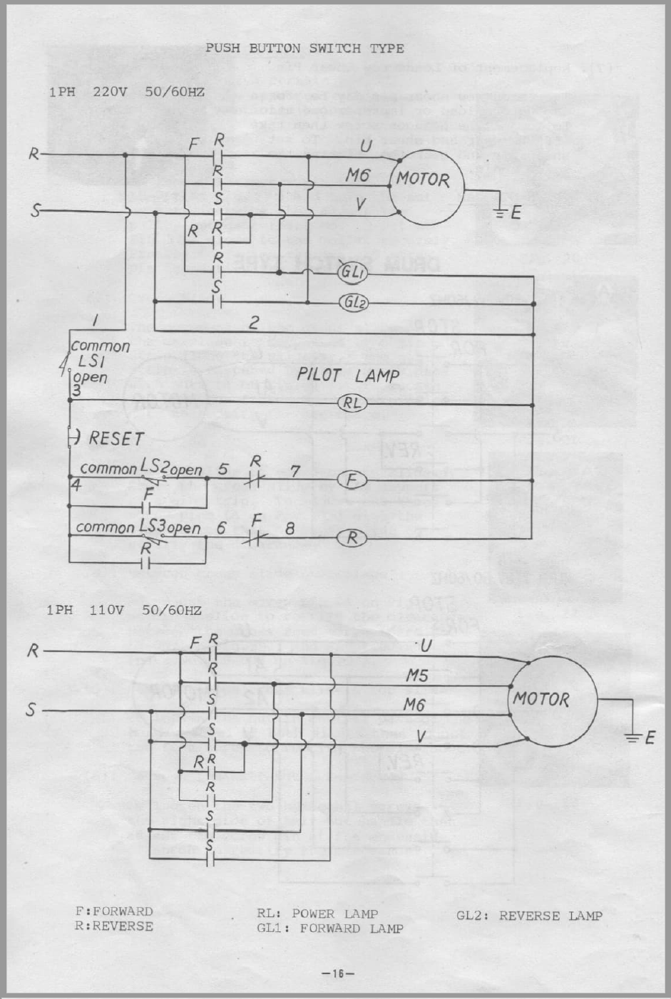
I found a Honden wiring diagram that seems accurate, but I am uncertain which pole controls the coil. The side terminals or maybe 13/14?

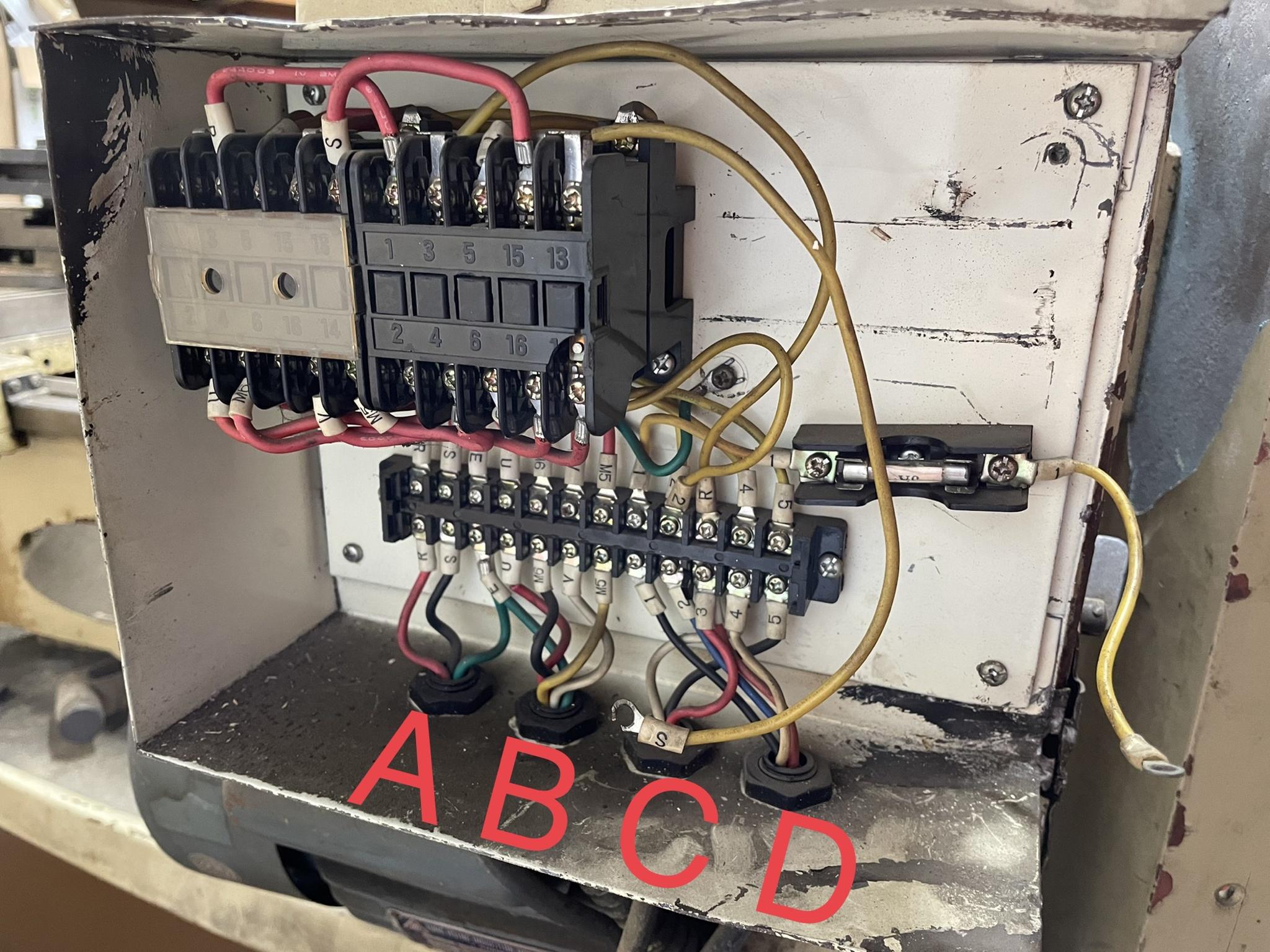
Also....in the picture, I labeled the conduits. I'm not sure I understand the role of "C"; it leads to a box under the power feed.


A: 110V in

B: Motor

C: Unknown

D: Power control (emergency stop)


tm5mt9ky


5zy2ez4p


af5rv56n


Thanks,
Alex
 
Hi Alex, what horsepower rating is the motor? I assume it's a dual voltage 120/240 type. I see what looks like the outline of a transformer above the fuse holder. Is it possible the orginal burned out and the PO removed it?
The contactors may be either 24 volt coils or 120 volt. I see some terminals in the back that might be the coils
-Mark
 
Hi PancakeCritter (Love the name lol),

Happy to help you with the wiring. I do industrial controls as a job so I am very familiar with this style of wiring diagram.

First off, I will assume that you are using this with 220/240VAC single phase (typical of residential appliance wiring). If you plan on running this at 120V let me know, but the amp draw will be pretty high.

There are a pair of contactors (big multi-pole relays for power switching) which control the motor. Depending on which is "pulled in" determines the direction of rotation of the motor.

Your AC power from your house is wired in at the terminals "R" and "S" on the left. Not shown is the ground, but that is very important and should never be omitted (safety reasons). If you are unfamiliar with grounding practices, let me know and we can chat about that more in detail.

The power feeds a pair of contactors labeled "F" and "R" for forward and reverse. Each symbol that looks like -| |- is a Normally Open (N.O.) contact. Don't love the terminal labeling in the diagram. Not obvious how it is wired.

Now from the looks of it, some parts of your cabinet have been removed. Also from the linked wiring diagram, your switches on the front of the machine are carrying the full 220VAC. That is OK, but not my preference. We might need to modify the wiring a bit.

Under the motor wiring is the control wiring. This shows all of the switches, buttons, lamps, and coils of the contactors. I would definitely make sure I had a 500mA fuse in line with wire #1. This would limit the fire hazard if one of the control wires were to short. I would also make sure I had appropriate overcurrent protection on terminals R & S. This should be sized not larger than 125% of the motor Full Load Amps (FLA) on the nameplate. For example if the motor draws 10A at full load, you would need an overcurrent protective device or upstream breaker no larger than 12A.

If you can give a few more pictures of the inside of the cabinet from different angles it will help to see what you are working with. Especially the terminal strip below the contactors.

-Mike


For reference, here is the wiring diagram out of my lathe - a bit different from yours since mine has a 4 wire motor.

1618513549357.png
 
We don't know yet what voltage the contactor coils are, and I hesitate to just go ahead and power it up without knowing for sure
I'm thinking a ohm test of the coils is in order first
-Mark
 
We don't know yet what voltage the contactor coils are, and I hesitate to just go ahead and power it up without knowing for sure
I'm thinking a ohm test of the coils is in order first
-Mark
100% agreed. Based on the condition of the wiring it looks like the panel is incomplete and needing attention. I'd like to see more pictures of the setup, including the contactors and motor, before I would advise doing anything.
 
Yep. May very well need to purchase another transformer too before we are done
 
Mark/Mike,
Thank you both for the enthused help! It may be of help to let you know I'm a mechanical engineer...but I'm not afraid of the pixies.

Mike,
For now, I'm planning to run on 110V. The motor is a 2HP 110/220V - 12/24A, so I'll need a 30A if I plan to actually utilize it on 110. I need to check the wire gauge that is run to this building before I do that. I'm hoping to run 220V to the building in the near future, but have some concrete surrounding the building so its more of a project than I have time for at the moment. My goal is to get it spinning, update the belts, clean everything up, etc.

The box does have a 5A fuse inline with #1, but I need to replace it. I do plan to replace/update the switches too eventually. I'll probably ohm the existing ones tonight to verify they're working correctly.

I do have some other pictures, but it will still be hard for you to see the side terminals of the contactors. I'll take more for you guys later.

The top two terminals are tied together, as are the bottom two. Top and bottom isolated, I think.

Not being at home, here is a quick sketch of the current contactor wiring, minus the top/bottom terminals. (coils)?
The yellow wires labelled "2" both go to the bottom terminal. The top terminal doesn't have anything going to it, other than being tied together.


4d4byubf
 

Attachments

  • Wiring.jpg
    Wiring.jpg
    2.3 MB · Views: 13
Last edited:
It is obvious that there was a control transformer in there and the two loose wires were attached to the secondary side of it, that infers that the controls are either on 110 or 24 volt, and you need to determine which it is, another thing, you need to determine if the motor is in fact dual voltage, it may not be.
 
It is obvious that there was a control transformer in there and the two loose wires were attached to the secondary side of it, that infers that the controls are either on 110 or 24 volt, and you need to determine which it is, another thing, you need to determine if the motor is in fact dual voltage, it may not be.
Here's the motor plate. The coil is 100V 50Hz, 100-110V 60Hz.
 

Attachments

  • Motor Plate.jpg
    Motor Plate.jpg
    175.8 KB · Views: 19
  • Coil.jpg
    Coil.jpg
    709.1 KB · Views: 16
Back
Top