2019 POTD Thread Archive

Did a bunch of googling for step key stock, and could only find a slightly better piece (current piece was to step between a 1/4" keyway and a 3/16" keyway, and the height of each step on the key was 3/32"). The slightly better key stock just increased the height of the 1/4" part to 1/8". From measuring the keyway in the impeller and the crankshaft, I could use one that was 1/4" x 1/8"high, and 3/16"x 5/32" high, so I tried my hand at fabbing one, using my drill press, an X-Y vise, and a 1/2" end mill. The setup looked like this:
IMG_1509.jpg
For those of you with so-called "wet noodle" mills, this setup would be as if you took those wet noodles, blended them into a paste, then boiled the paste for a week.

Anyway, after several attempts, I figured out to tighten down the gibs on the vise, up the speed on the drill press to about 600 rpm, take fairly shallow cuts, and only in one direction, and eventually I managed to produce something not too bad: (left is the original keystock I bought, right is the newly fabbed bit)
IMG_1510.jpg

Now, I just have to clean up the impeller and adapter I made, as they were slightly damaged when the key sheared, and then I'll give it another go.
 
Reassembled one of the hydraulic pumps for my Husqvarna walkbehind mower (that I am also slowly making a brush attachment for), and got all the parts cleaned for doing the other one:
IMG_1512.jpg
IMG_1513.jpg

The gasket kit for these pumps includes bits for a number of other pumps as well. Naturally, I picked the wrong seal for the trunnion lever (rod sticking out the "top" of the first image), and after spending some time forcing it into the housing, warping it in the process, I then realized it was the wrong one, dug it out and installed the right one which was just a smidge smaller, and was installed with no fuss at all.

As a bonus, right after I had completed assembling it, I dropped the unit on the floor, and nicked up one of the hydraulic fittings, which of course are also a fairly unusual type of connector (37 degree flare with an o-ring on the end, I think I found one company that sells them under the brand name of "Flare-O"). I think I've found a local company that sells these things, so I'll go there on Monday and see what they've got. I also should get new O-rings for the rest of the fittings, as all the existing ones look permanently deformed from use.
 
Today I made chips :D

The side effect of that were some end-caps for my DRO 10mm magnetic scale.

I guess it's tome to clean...
9890664c53ef069119eb7b0cbcd57c61.jpg
e4022037e23e53c7b9724c74d4d2e60f.jpg


Sent from my SM-A520F using Tapatalk
 
Drilled and tapped an M3 thread. Hard work indeed

End-caps first test fit is looking good.

Dedicated grooves for fitting the encoder strip were already foreseen in the mill castings, so the actual install will be super easy.

fa23e00db11f04124eb822a57c3005c5.jpg


Sent from my SM-A520F using Tapatalk
 
Improved a ceiling mount for my wife's projector. She leads several ladies bible studies each week. The one that I had scabbed together before worked OK but taking it on/off was not easy to adjust with the wires.
DSCF4104.JPG

So I made one from aluminum tubing. Now it is as easy as just setting it in place (no adjustment)!
DSCF4106.JPGDSCF4107.JPG

The 3 screws are put dead center in a knot so when it's no longer needed, a little dark filler in the hole and no one will ever know there were screws in the beams.
 
I am being treated for two types of cancer for longer than a year now and it has kept me out of the shop - I cant think and hardly have the strength to walk---- and I had forgotten about this group.
I am presently making 20 of something -tool and die work-... I don't even know what they are although I have made them before. Worse , I having a tough time remembering some details of using autocad and my cnc mill . And I was good at all of this before the chemo infusions..
Impressive that you're motivated to get back into your shop. Stay strong.
 
POTD was a long overdue refurbishing of my Craftsman 10” table saw side/outfeed tables. The saw comes stock with a fence for ripping up to 24” on the right side of the blade. After making kitchen cabinets for multiple houses by scoring oak ply and cutting with a circular saw at 34 ½”, I upgraded the Craftsman saw with a 53” rip capacity Beisemeyer fence. My saw came with stamped sheet metal LH/RH side feed tables and no outfeed table. I made new tables from ¾” particle board with oak aprons and a laminate top. My saw is mounted to an angle iron base that also carries a 6” joiner. I did a really poor job on the far side of the RH table for support by adding a hinged stick to stabilize the saw. The fence is really hanging out in space. The Craftsman saw base is sheet metal and pretty flimsy when I’d work on the far side of the side table. The simple solution was a hinged leg. I’d swing it up out of the way to push the saw around; not a very elegant solution but the saw was mainly stationary.

Our original pole barn is 40’ x 56’ x 10’ high with a shingled roof. My shop occupies the front 32’ feet for a 32’ x 40’ shop. We re-roofed it with steel panels 6 years ago to match a 40’ x 40’ x 12’ addition on the back. Our son and I got the roof on in a day. Unfortunately, I didn’t get the ridge cap on and we had a thunderstorm that night. How much water can get into a 3” wide by 56’ opening at the peak of the roof? A lot more than I expected, the table saw was setting in the center of the shop and got at least a gallon of water dumped on it. I wiped it off the next day and put paste wax on the table. Few weeks later I tried ripping a board and had a “clunk” as the board hit the lead edge of the outfeed table. The particle board tops got wet and swelled up at least 1/8”. So, pull the laminate and belt sanded the high spots to get a workable saw again.


The "before" of my 10" Craftsman table saw. Love the 53" rip capacity of the Beisemeyer fence, but my hinged support stick was "cheesy" to say the least. Plus, poor planning on my part resulted in the saw taking a shower which swelled up the particle board support tables. Pulled the laminate and sanded it down, but had much more friction than the waxed plastic surface.
20191012_135827.jpg20191012_135844.jpg


We have a local metal scrap yard who had a pretty good supply of Creform tubing and fittings for pretty cheap ($0.25 per coupling, $0.25 per foot for the tubing). Google “Creform” if you’re interested in learning more. Pretty nice stuff for throwing together pretty strong racks and tables very quickly. The tubing is about 1 1/8” diameter with a 1/16” wall.

Pulled the old tables and started with a pre-laminate piece of ¾” particle board. Made aprons from stock on hand; oak and walnut. Nothing Earth-shattering about the construction, cut to size on the saw and screw in place. I broke all of the exposed edges with a radius plane called “Slickplane”. It has an angled shoe made from brass bent at a 90. Has two carbide tipped blades with about an 1/8” radius on the end. You adjust the depth of cut so the work is started by the lead bit and taken to full depth by the second.


Made up aprons from oak and walnut on hand. Miter clamps to hold square, hand screw to clamp the apron to the table top and drill/screw together.
20191012_145504.jpg

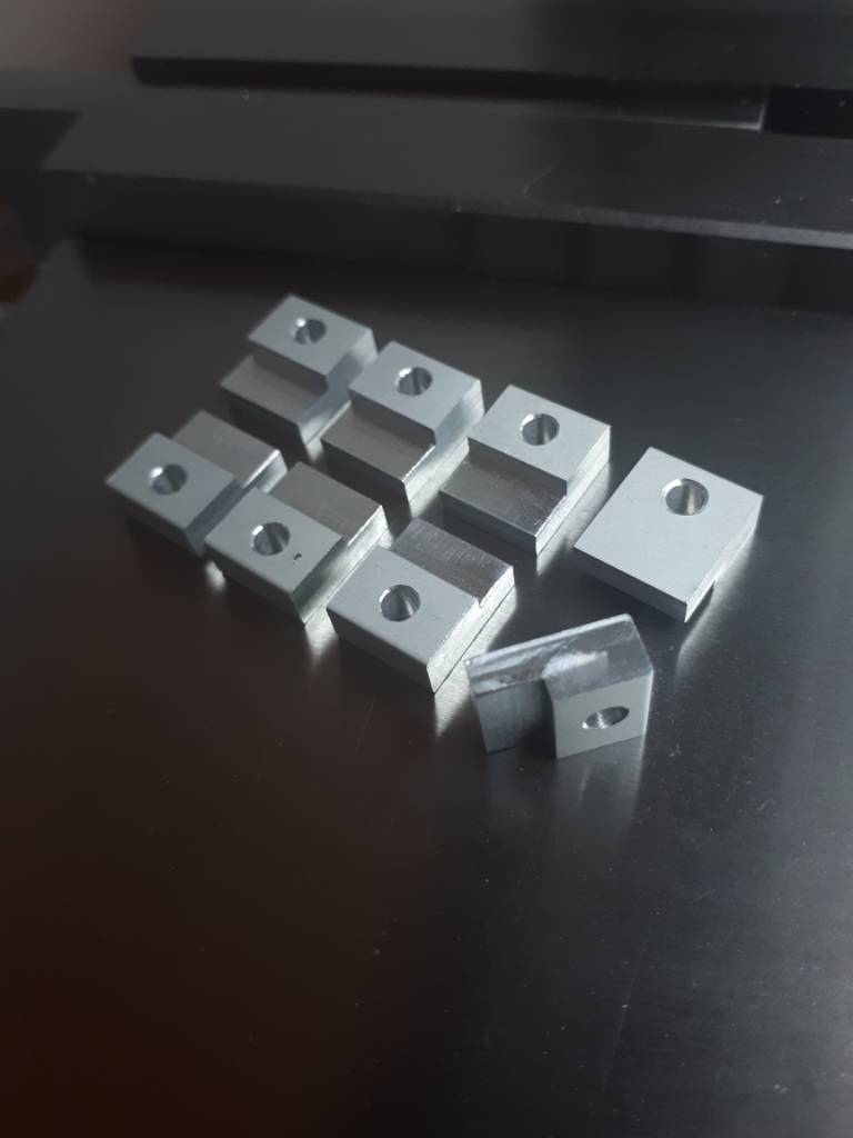
Made s support brace for under the RH table for attaching bracing back to the angle iron brace. Salvaged the angle from an old 12-ton HF shop press.
20191013_112138.jpg

Old table out of the way.
20191013_141502.jpg

New table set in place. Put a piece of masking tape under the wood stand-offs to shim the side table slightly below the cast iron table.
20191013_150809.jpg

Clamped a couple of straightedges to the table tops bridging the cast iron and new side-feed table. Then drilled and screwed the table aprons to the angle iron seen above.
20191013_151236.jpg


My initial thought was to support the large side feed table with no vertical legs, just a pair of angled Creform tubes running down to the angle iron legs. Welded up a support bracket for under the extension table from angle and bolted it together. It’d was “okay”, but wasn’t as stable as I’d like. The weak point is the sheet metal Craftsman table saw base. So, added two legs which make it rock solid. They are hinged and clip to the angled supports when moving the saw.


Original set up with no vertical support legs. It worked "pretty well", but leaning on the end of the table flexed the sheet metal saw base. So . . .
20191013_164121.jpg

Cut some more Creform tubing and attached to hinged vertical legs. These fold in toward the angled bracing and clip in place, makes for pretty easy moving of the saw.
20191018_162434.jpg


My original outfeed table was made with really no forethought on size. It extended about 35” from the back side of the table saw blade. “That should be good enough to balance an 8’ sheet of plywood’. It wasn’t . . . so the new outfeed table extends to 50” past the back of the blade. Now I can rip a sheet of plywood and not have to push down on the back side to keep it from lifting off the table.


Started by ripping the apron board so it was just below the cast iron table top with a piece of the 3/4" particle board/laminate. Drilled holes for 3 attachment points to the saw.
20191019_123938.jpg

Made heavy use of a Slickplane to break the edges of all the hardwood aprons. Nicer to bump/rub your hand or arm on a 1/8" rad instead of a sharp edge.
20191019_130632.jpg

Bottom side view of the out feed table
20191019_151039.jpg

Routed a couple of clearance slots for the miter gauge.
20191020_102221.jpg


The new out feed table makes the footprint of the saw about 7’ x 9’, so a pretty big area. I used more Creform with casters for the outfeed table; three bolts attach it to the rest of the saw. It’s pretty quick to use a Milwaukee ¼” M12 ratchet to pull the bolts and roll the table out of the way separate from the saw. Also makes for a nice, quick work bench.


Finished saw table refurb. Really nice to get the table tops back to laminate covered. It's like sliding boards over an air hockey table.
20191020_170849.jpg


All in all, pretty happy with the results. Thanks for looking.

Bruce
 
POTD was making pivoting legs for a 10’ piece of skate conveyor I use for a side support table at my table saw. It’s so nice to be able to throw a 4’ x 8’ sheet sideways on the saw and cross cut it by myself. I’d done a crappy job with the supporting legs, time to do a better job.

Used more of the Creform tubing and attaching brackets from a local metal salvage yard. Initially I did the legs straight down at the width of the roller conveyor, but it was a bit too tipsy side to side. Cut some tubing to make a wider base. I didn’t show the work, but turned some bushings so one of the joints could be clamped tightly and still pivot. The attachments to the conveyor rails are pieces of angle iron, hinge is a loose bolt with a nylock nut. It is very solid and stores pretty easily.


Skate conveyor upside down showing the new legs extended.
20191020_170905.jpg

Legs folded up for storage or transport.
20191020_171024.jpg

There are a couple of pockets that the legs hinge up and drop into. I ended up drilling holes through this bracket after the fact to pin them in place when in use. Yeah, picked up an end to position the table and the legs folded up.
20191020_171032.jpg

The legs have adjustable feet to level the table to the table saw.
20191020_171055.jpg

Great to have the space to swing a 4' x 8' sheet for cross cutting or ripping by myself.
20191020_171607.jpg


Thanks for looking,


Bruce
 
Back
Top