5 cylinder Radial Engine

Thanks Chris

David yes a CNC machine is very useful but I have only used it for the master rod and now the ring gear for this project. All the other work was done on a manual mill and lathe.
Ray
I have worked with the design tools . I am more impressed by the creation of the design files for input to CNC.

Great job so far

Will
 
Hello Will good to have you along.

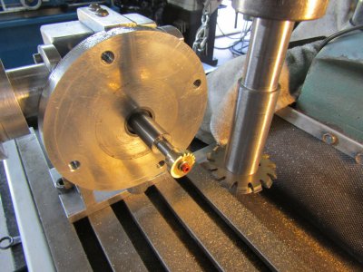
Making a 19 tooth gear for the crankshaft.
IMG_1497.JPG

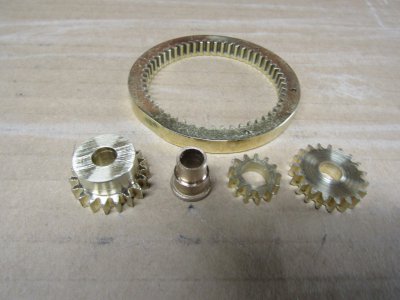
These are the parts that makeup the valve timing for the engine.
The 13 tooth and the thin 19 tooth gears are pressed on to the Oilite bushing. The big 19 tooth gear goes on the crankshaft.
IMG_1500.JPG

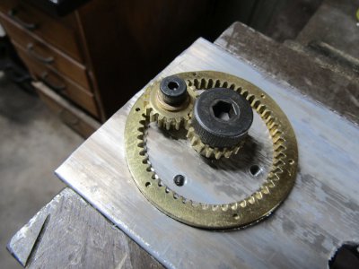
This is the test plate I made up to check the gear spacing. The ring gear fits in a slot and the large gear is in the center where the crankshaft would be. I drilled 4 holes of different distances from the center to see which one would work the best for the idler gears. It turned out that the 0.750 from the center was the best fit. This tells me where to drill the hole for the idler gears in the main housing.
IMG_1502.JPG

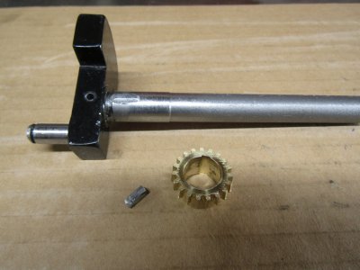
Milled a 1/8" key way in the crankshaft and bored the crankshaft gear to size. Then filed a recess for the key in the gear.

IMG_1504.JPG

Thanks for looking
Ray
 
Nice job, Ray!

You trying to put the pressure on me to finish mine or something??? ;)

Following along.
 
JRaut glad to have you along. I have read through your thread on this engine several times and that has helped me visualize some of the drawings. No pressure just doing my own thing.

Chris you are too kind.

Ray
 
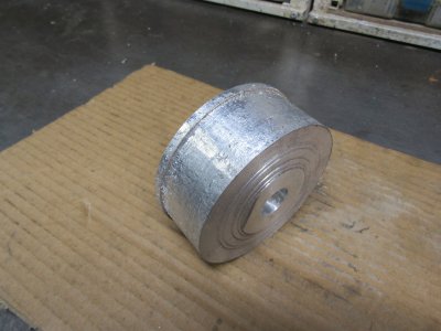
I found this rather ugly piece of aluminum in the (save it I might use it some day) drawer to make the cam housing.
IMG_1508.JPG

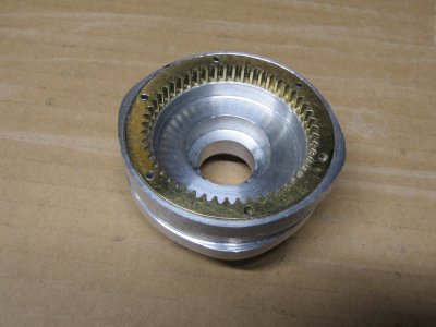
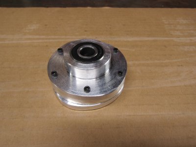
Several hours of work later and the housing was completely machined with all the features except for the cam lobes.
Over on the CNC I cut side number one and it turned out great with nicely shaped lobes. Since there is an under cut the part has to be turned over to do the other side and the other two lobes. I flipped the part over and cut side number two and it turned out great also.
IMG_1510.JPG

As I was admiring my handy work something didn't look right. When I flipped the part over I didn't get it clocked correctly in the vise so instead of the cam lobes being 60 degrees apart they were 90 degrees apart. In order to maybe salvage the housing I thought why not cut the housing flange off and re drill the holes offset by 30 degrees and here is the result.
IMG_1515.JPG

The cam lobes are in the right place now but the ring gear is not exactly running true and that is very important.

Time to start over

Thanks for looking
Ray
 
Practice...

Sent from my SM-G781V using Tapatalk
 
Never start with ugly aluminum.
 
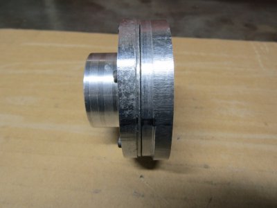
I took your advise Robert and cut this piece out of a nice looking chunk this time.

Happy Days
Practice makes perfect or just about as this time every thing worked out fine. The bumps are in the right places and everything fit as it should. I was going to polish it but then changed my mind as no one will ever see it but me.
IMG_1517.JPG

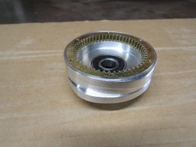
And the other side.
IMG_1520.JPG

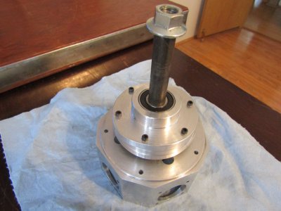
I made a spacer from the crankshaft gear in the main housing to the cam housing bearing to get the height correct. I also made a spacer for between the two cam housing bearings and a long spacer for the nut to bear on. So when you tighten the nut there isn't any side load on the bearings. The shaft actually turns quite well with just one tight spot for every fourth turn of the crank.
I won't really know how well the gears mesh until I have the outer nose installed that has the outer crank bearing to hold everything in alignment.
IMG_1522.JPG

Thanks for looking
Ray
 
Back
Top