[How-To] 5hp 3-phase AC motor & VFD control question

Nightshift

Active User
Registered
Joined
Jan 26, 2012
Messages
87
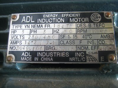
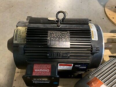
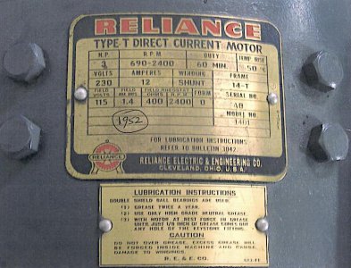
I've been reading up all the info I can here about converting my Monarch 10EE DC drive system to 3-phase AC with VFD control. The 3 hp Reliance DC motor works fine but my custom-built DC controller is becoming a real headache and impossible to troubleshoot. I looked into a new DC controller but found this was very expensive and since I already have a 5hp 3-phase AC induction motor I will buy a 10 hp rated (2x factor) VFD to power it since the input is single phase. At this point I'm not planning to adapt it to my gearbox so will start out at least driving spindle directly from the motor. If I find down the road it doesn't have enough low end torque for threading I can always adapt the backgear to add back in.

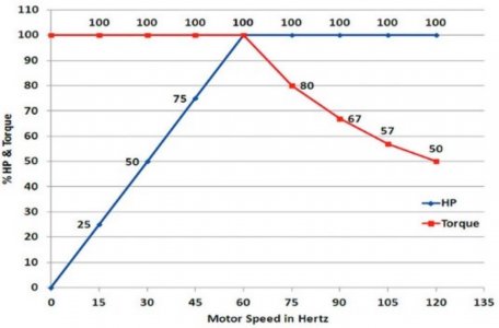
The 3-phase motor I'm planning to use is 1740 rpm. Looking over Karl_T's 10hp direct-drive install, his motor is about the same rpm at 60 hz as mine, and he has put a 2.3" OD motor pulley belted to the 7" spindle pulley for a 2.5 ratio. I'm trying to understand how you get the spindle up to 2500 rpm and the only way I can see to do that is to overspeed the motor by feeding it 3x the hz. Is this correct?

The 2nd question I have is to determine what brake resistor I might need since the 2 resistors on the lathe now are not likely the right size. I understand you can set the VFD accell/decell times but an external brake seems to be a good idea on a lathe where you want it to stop quickly. Is there a simple calculation to determine this? Bill
 
The issue with a standard 3 phase motor and over speeding it is that the Hp will be maintained to around 90-100Hz and then typically will decline. They also have threamal limits based on the cooling design. Motor bearings are the same as a 3600 RPM motor, and usually are good to around 4500 RPM (3600 RPM motors are allowed a 25% over speed) but there may be issues with stator balance issues above this speed. An inverter/vector type motor are rated to around 6000 RPM on motors up to 5 Hp, 7.5/10 Hp it varies but somewhere in the 5-6,000 RPM and will maintain full Hp up to this maximum RPM. They also will maintain a constant torque ratio in the range of 1000:1 or greater so pretty much full torque down to almost 0 speed. Standard inverter motors have a CT ratio of around 4:1 to 10:1. So using an inverter/vector motor will give you a much wider speed envelope with very good performance, Hp will decrease linear below the base speed of 60Hz but with full torque and Hp will be maintained above the base speed but torque will fall off. Typically these motors will be TENV, TEBC or may be TEFC but with heavy construction to allow greater heat dissipation. The inverter/vector motors that I have used are the Baldor (IDNM), Lincoln, Marathon Black/Blue Max series, ABB/Reliance similar to what Karl used, Teco also has the MAX-E1 series which are often under the radar with most shoppers.

Typically as the motor poles increase so does the size of the motor and the stator, which limits the top speed. In most cases you want to gear down the motor and run it in the 20-200 Hz to maintain optimum performance, in addition to over sizing to compensate for Hp loss below the base speed. Inverter-vector motors can also be driven harder into overload, so I typically run 180% overload in the VFD parameters. These type of motors typically have thermal sensors that can be wired into the VFD if the temperature gets too high, but in these types of applications they will stay very cool.

As far as braking resistors, the size and wattage is described in the VFD manuals for the particular brand/sized VFD, since the braking is not sustained but only over a few seconds you do not need large dissipation resistors. If you are driving a 5 Hp motor than you would use a 10 Hp 3 phase VFD (assuming derating for single phase input), So something like the WJ200-075LF, the lowest ohms would be 17, but the range would be something in the 17-35 ohm range and a minimum of 500W. The wires will have upwards of 380VDC and can be pulsed with momentary currents on the order of something like 10-20A, so a minimum of 12AWG 600V wire. I often use metal encased power resistors available from most electrical distributors.

Inverter Duty motors.jpg
 

Attachments

  • WJ200_Dynamic_Braking_Selection_Table.pdf
    58.8 KB · Views: 10
  • Hitachi Brake resistor Selection Chart_Jan 2013_ROC revised.pdf
    303.9 KB · Views: 5
Awesome explanation. Very much appreciated. Fills in the blanks for me on this. Since I have a 5hp motor already, I just need to decide now if to use it directly without the gearbox and determine the motor pulley size to achieve reasonable torque at the low end and 2500 rpm at 180hz. Or I might just do the work now and adapt the gearbox since 5hp is on the smallish side to run without it. Appreciate the expertise here. Bill
 
The motor I have already is a TEFC chinese version. Its been sitting for years as I originally intended using it to make a RPC ... this was long before I discovered VFDs about 10 yrs ago. If I didn't already have this, I would go and buy an name brand NA made motor. My label says its an induction motor but I don't understand what that means compared to the vector/invertor duty motors you mention. Here's the label and perhaps you can give me you option if this is worth using or I should just flip it for an invertor duty one. Cheers, Bill
 

Attachments

  • 5hp 3-phase Motor.JPG
    5hp 3-phase Motor.JPG
    1.2 MB · Views: 15
I got this link from one of you guys which is excellent for amateurs like me to visually explain the relationship between torque and hp as you adjust the frequency below/above 60 hz. Bill
 

Attachments

  • Screen Shot 2021-04-28 at 10.21.51 AM.jpg
    Screen Shot 2021-04-28 at 10.21.51 AM.jpg
    135.6 KB · Views: 18
Not really an inverter rated motor, would work but the performance will most likely fall off beyond 90-100Hz, wouldn't go past 120 Hz or below 20 Hz. Inverter duty/vector motors are designed for much wider speed range and also able to maintain their performance. Some are inverter only, others can be run across the line if needed, they typically will have a small jack shaft on the back of the motor for an optional positional encoder. Almost all are TENV, TEBC and a few may be TEFC. Some examples below, most are best offer so you can probably get a new motor for around $500 but shipping will be an issue for you. If you use the motor you have, I would use the gearbox for the low speed range. You need to carefully check the motor name plate for voltage and specifications.


One thing you can do is calculate the torque on your existing DC motor. Not sure what RPM the 3HP motor is rated at for full RPM before field weakening. I'd guess that it is rated at about 1000 RPM (my 5HP is rated at 1140RPM IIRC).


H = T x rpm/5252, H is horsepower, T is torque in foot-lbs.
T = H*5252/rpm.
So 3HP @1000 RPM is 15.76 ft-lbs torque.
If you run the backgear at 5:1 with the motor at 1000RPM, you get 200RPM @ 78.8 ft-lbs torque.

If you know your pulley ratios you can figure what torque and rpm that gives you at the spindle. This will give you a good idea of what you are getting now. Then run the same numbers for your proposed motor HP and pulley setup, with or without the backgear. That will give you a good idea if you're getting the same performance.

This is back of the napkin numbers for the sake of comparing motors, so it ignores things like gearbox inefficiencies, bearing losses. Also the DC motor has a different torque curve than what you posted for an AC motor and VFD, DC motors typically *increase* in torque to some extent at lower RPM, but that depends on series vs shunt windings. Regardless, if you work the numbers for those two data points (full RPM w/ and w/o the backgear) you'll get a good idea of what the current configuration does.

If you post your existing DC motor dataplate and pulley sizes, I'd be happy to help crunch some numbers
 
Thanks for the guidance mksj and rabler. Appreciate the help on this.

Here is the current DC motor in my lathe now. Armature is 690 RPM. Motor pulley is 6.5" and spindle pulley is 7". Bill
 

Attachments

  • Reliance DC Motoe 3HP .jpeg
    Reliance DC Motoe 3HP .jpeg
    85.9 KB · Views: 14
Currently

Motor RPMMotor TorqueSpindle RPMSpindle Torque
69022.8 Ft-lbs64024.6 ft-lbs
69022.8128 (5:1 reduction gear)123 ft-lbs


Some AC motor comparisons
HP @ RPMMotor TorquePulley Ratio,
Spindle RPM,
Spindle Torque
Reduction/
Spindle RPM /
Spindle Torque
Spindle RPM
@ 150 Hz
Spindle RPM,torque
@ 10 Hz
w/o reduction
5 @ 176014.9 ft-lbs1:1 , 1760 ,14.9
5:1 , 352 , 74.5
4400 293 , 14.9
5 @ 116022.61:1 , 1160 , 22.65:1 , 232 , 1132900 193 , 22.6
5 @ 176014.9 ft-lbs2:1 , 880 , 29.810:1 , 176 , 1492200 146 , 29.8
5 @ 176014.91.8:1, 977, 26.89:1, 195, 1342440 162, 26.8
7.5 @ 176022.42:1 , 880 , 44.810:1 , 176 , 2242200 146, 44.8
10 @ 176029.82:1 , 880 , 58.610:1 , 176 , 2982200 146, 58.6
10 @ 176029.81.8:1, 977, 53.64 9:1, 195, 2682440 162, 53.6

I picked a few numbers out of the air. These numbers are ballpark (back of the napkin) numbers for comparison. IIRC, some of the reduction gears are 5:1 (what I used here) and some are 6:1.

First column is just what a perspective "new" rated AC motor nameplate gives for 60Hz.
Second Column is what torque that motor develops at 60Hz.
Third column is a pulley size ratio, and the spindle RPM and torque for that pulley
Fourth column is same pulley size as column 3, plus putting the reduction gear in low. Ignore this if you leave out the reduction gear.
Fifth column is a Spindle RPM if you drive the motor at 150Hz with the pulley ratio from column 3. Roughly max spindle for a motor nameplate 4200rpm max as in two Marathon motors mksj linked to above. Your current DC motor and pulleys should run you about 2500 RPM max if everything is working correctly, so I tried to shoot for numbers in that ballpark.
Six column is what RPM and torque you get if you set at a lower frequency (10Hz) but don't have a reduction gear. It's not the minimum RPM.

So roughly speaking, a 5HP/1760 rpm motor, with a 1.8:1 pulley ratio and keeping the reduction gear, is a pretty close to the same performance (slightly better) as 3HP DC motor with the reduction gear. A 10HP motor w/o the reduction gear has about 1/2 the torque at low end compared to the DC motor plus reduction gear, but does have a lot more torque at higher RPMs than the DC motor.

A pulley ratio of 7" on the spindle and 3.5" on the motor would give you a 2:1 ratio. Or 3.9" on the motor for 1.8:1. I'm not sure what a reasonable lower limit on pulley size is for the v-belts, you'd want to double check that. Probably just a matter of belt life.

If you're never loading down the existing DC motor, you may be fine with less torque in a AC motor/VFD setup.
Lots of numbers, so feel free to ask if this is confusing!!
 
Last edited:
If you're thinking of re-using the reduction gearbox, you may want to open it up and check the gear wear. My reduction gearbox has one of the reduction gears worn down to knife edge teeth, so I need to repair or find a replacement before long. That may influence your decision!
 
Back
Top