- Joined
- Nov 9, 2018
- Messages
- 377
Thanks for the info.
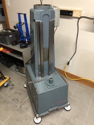
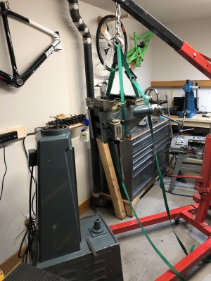
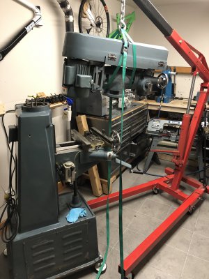
I was thinking about just lifting it out by hand, looks like it probably only weighs about 100 lbs or so (I deadlift 300 ), but maybe a hoist is smarter, like the hook idea.
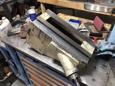
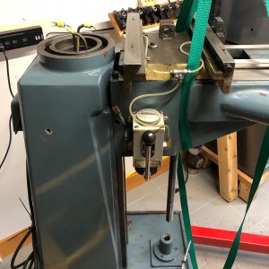
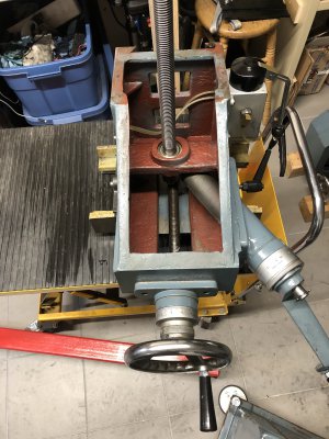
It almost looks like with the gib removed it might slide straight out.
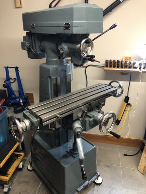
I originally just planed on scraping the top ways on mine because they were damaged from previous owner, but I’ve now found out that the knee is tilted sideways by about 0.015 over 8”, no wonder I could never machine a square part with that knee.
Got a thread of my disaster here:
 www.hobby-machinist.com
I was thinking about just lifting it out by hand, looks like it probably only weighs about 100 lbs or so (I deadlift 300 ), but maybe a hoist is smarter, like the hook idea.
It almost looks like with the gib removed it might slide straight out.
I originally just planed on scraping the top ways on mine because they were damaged from previous owner, but I’ve now found out that the knee is tilted sideways by about 0.015 over 8”, no wonder I could never machine a square part with that knee.
Got a thread of my disaster here:
Grizzly G0678 8x30: Repair, Scraping and Alignment
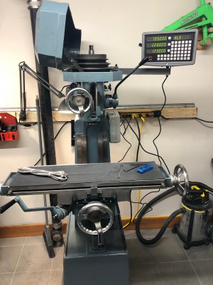
to be honest so far I've been pretty impressed - the nod was out by a touch, so I sorted that out with a piece of 7-up can between the knuckle and the base, which put it within 0.01mm over the width of the table. All the sliding surfaces are in good condition, no gouges or ugly machining marks...
www.hobby-machinist.com
Last edited: