90 degree V Twin build

rdean

Active User
H-M Supporter Gold Member
Joined
Feb 2, 2014
Messages
1,061
I just have to build another engine so if you are game then follow along and comment.

This is number 6 of the engines I have built in the last 2 years. I got hooked bad and there doesn't seem to be any way to stop.
This build will be a V Twin engine with the cylinders at 90 degrees to each other. The crank shaft is a 180 degree style with apposing throws where as many of the V engines have one crank throw for both cylinders. I understand that this configuration is not too common so we will have to see how it all turns out.

I have been asked about plans for some of my other builds and I don't have any. I design and build as I go long but I did make a drawing for this engine to see what size material I would need and kind of how things would fit together.
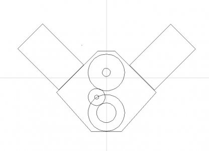
Drawing.jpg
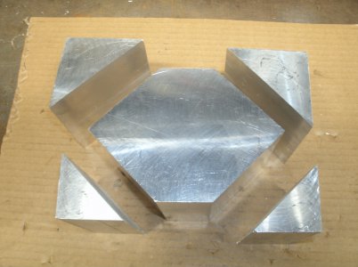
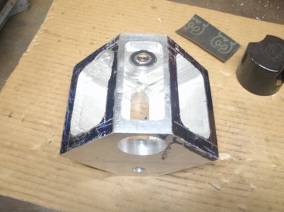
I started with a block of aluminum that was 6" X 5" x 4" and cut away pieces that I didn't need.
HF band saw worked great.
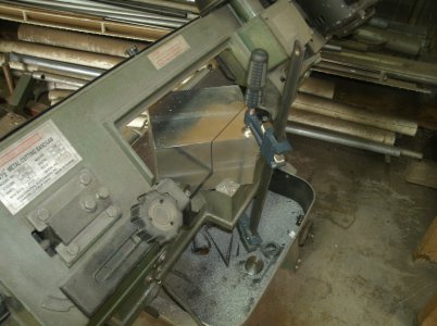
GEDC5297.JPG

I had to get creative to hold the block in place.
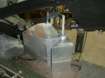
GEDC5302.JPG

Four cuts in all.
GEDC5306.JPG

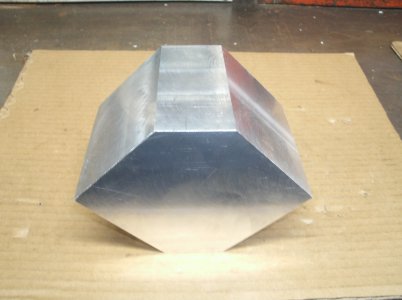
And this is what is left.
GEDC5310.JPG

There is a engine in there some place.

Thanks for looking
Ray
 
Essentially, you are building a Harley V-twin. Except for the seperate crank throws. Having a crank bearing between leads to interesting possibilities. I have seen (thanks Internet) several scale Harley engines. Your idea is well worth following. I will be watching from the shadows.

.
 
In December of 2020 I built a flat twin cylinder model like a two cylinder Volkswagen engine but I was never happy with it. It did run and some times quite well but the o-rings could not handle the crank case oil that was thrown right up into the cylinders. I made some changes to the oil pan and lowered the oil level and that helped but then the crank shaft started giving trouble. I repaired that and then one cylinder would loose compression probably because the piston was not machined properly. (my fault) Long story short I decided to dismantle that engine and use some of the parts on this engine.
This engine will have a 1" bore and a 1" stroke and I have some catching up to do as I started this build last week.
So don't think I did all this work in just one day.
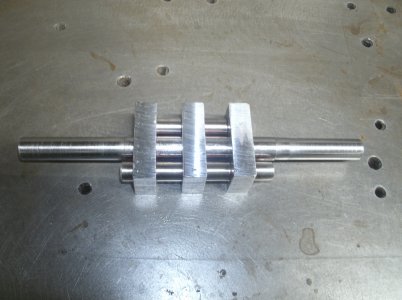
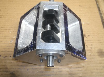
I made up a new crank shaft with all pieces pined with 1/8' dowels and loc-tite together.

GEDC4714.JPG

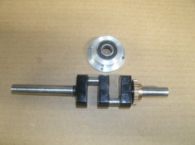
Here it is cut away in the right places, painted, and the old crank shaft gear installed.
I made a new crank shaft retainer and bearing.
GEDC5338.JPG

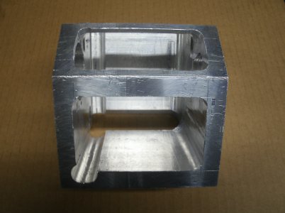
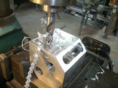
After a day and a half of making mounds of aluminum I had the block roughed out as close as I could with the end mills I had.

GEDC5317.JPG

Here it is with the crank shaft installed.
GEDC5318.JPG
I did get a 5" long 1/2" end mill in the mail.
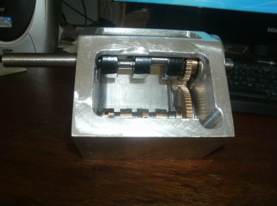
After another day of milling I have the inside of the block to my liking.
The slots are for the cam gear clearance.
GEDC5320.JPG
We are almost up to date.

Thanks everyone
Ray
 
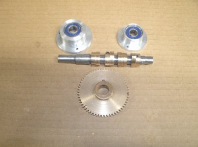
I will be using the cam shaft, cam lobes, one end plate and the cam large timing gear from the other engine.
I made the large end plate as the other one would not fit this engine.
GEDC5335.JPG

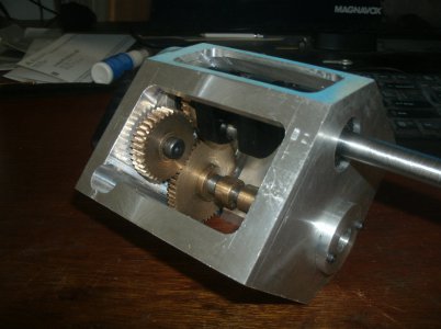
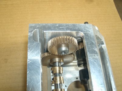
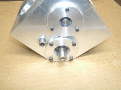
Since the distance from the crank shaft and the cam shaft is further apart on this engine I will cut an idler gear to make up the difference.
GEDC5323.JPG

The gear is made double wide as the crank and cam gears are not in line with each other.

GEDC5326.JPG

A better angle to show the offset of the gears.
GEDC5328.JPG

Yes I have a round column milling machine and I am sure you have seen many modifications to and heard all the negitive reasons why a square column machine is better than a round column and on rare occasions that is true. Most of the time with just a little planning ahead the head doesn't have to be moved.

Cylinder holes and mounting bolts.
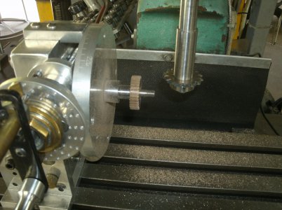
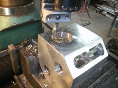
The first step after locating the center of the cylinder is to drill a 1" hole using an R8 collet.
GEDC5340.JPG
Next comes the boring head.
GEDC5343.JPG

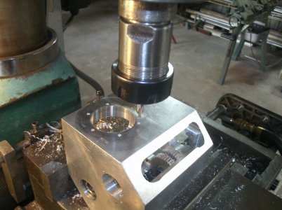
And last a center drill in a ER32 collet to mark the cylinder bolt holes.
GEDC5347.JPG
The head was not moved.
More to come
Ray
 
Design Change

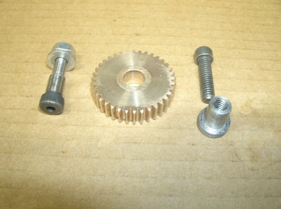
The idler gear for the cam shaft was originally attached using a 5/16" shoulder bolt that had 1/4" threads. In order to get the gears to mesh nicely I had to elongate the 1/4" hole in the block wall for adjustment. The small difference between 5/16 and 1/4 in an oversize hole was asking for trouble as the gear was hard to adjust and not square to the wall.
That idea was scrapped so I bored the gear out to 3/8" and made a steel bushing to retain the gear. I then threaded the inside of the bushing 1/4" X 20 for an allen head bolt. The larger base of the bushing covers the elongated hole and it looks better.

GEDC5354.JPG
From the inside.
GEDC5356.JPG

Cleaner outside also.
GEDC5359.JPG

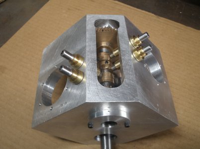
I was able to reuse the brass valve lifter bushings along with the along with the lifters.
The lifters may be a little long but we will see.
GEDC5363.JPG

At this point after all the major holes have been cut I usually disassemble the engine back to the bare block and paint it.


We are now up to date
Thanks for looking

Ray
 
Thank you all for following along and comments are welcome.

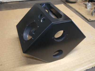
Just a short day today as I painted the engine block and I can't seem to keep my hands off things until the paint drys. So I quit early so I wouldn't be tempted.

I did chamfer most of the edges of the block before I painted it to make it look nicer.
GEDC5368.JPG

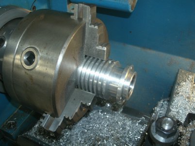
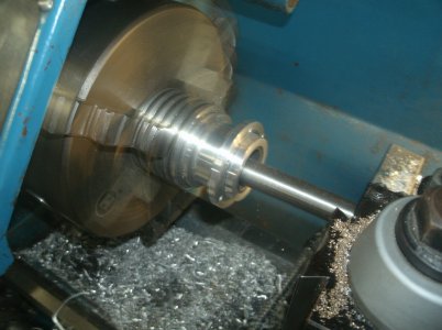
The cylinders had to be modified for this engine and one of them had a good scratch in the liner so I bored out both cylinders 0.020 over.

GEDC5365.JPG
GEDC5367.JPG

That's all for today

Ray
 
Back
Top