9A project completed

derf

Registered
Registered
Joined
Oct 3, 2015
Messages
982
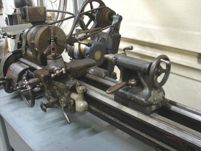
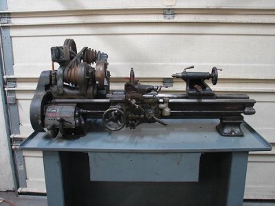
Some of you guys may remember this little crudball I acquired back in April...
DSC02504.JPG
DSC02505.JPG

I had just completed the last project, the Seneca Falls #30 resto-mod,(project of the month) when this lathe found it's way to me via a friend of a friend. My friend, who is also a tool salesman, showed me a pic of this on his phone, which came from his friend, the seller, who now is a retired tool room supervisor. He had this in his back building just taking up space and wanted the room for some of his restoration projects.
I told him I would take it, and explained to him what my mission was. With the lack of training facilities and instructors to teach skilled trades these days, my mission is to educate a passionate individual some skills that seems to be disappearing more every day, if I have to do it one student at a time!
I already had a student lined up to not only learn, but to eventually purchase this lathe once we got it up to date. He thought this was a noble plan, and let me have this machine for a very obscene low price.
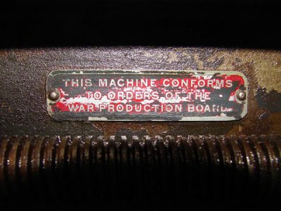
He also done the research and got the pick card from South Bend. This model was made in 1945. It left South Bend in March of '45 and went to Reynolds Machinery in Cleveland. In April, it went to Neil Machine of Lima, Oh. Neil Machine was a defense contractor that had a Navy contract to build tow targets for aerial gunners to practice on.
DSC02509.JPG

I don't know how long it stayed there, but it changed hands a few times and it was at a local school for awhile, until he purchased it.

Although quite filthy, everything seemed to be there with no missing parts on the lathe itself. But it didn't have much tooling. It has a 6" Union 3 jaw chuck, but with only the large diameter outside jaws. The chuck is actually pretty tight with little wear, but the killer is it only has the one set of jaws. Other than that, it came with a #2 morse dead center and an Armstrong lantern tool post, with one holder and 3 pieces of hss tool bits....almost bare essentials.

When I acquired this, I thought it would make another winter project, but I was wrong.....since this butted right up to the completion of the Seneca Falls project, I couldn't stop.....like Lays potato chips, can't eat just one! So I started in right away. more to come.
 
Nice project! I like your plan of training a person to run it properly!

I think a good manual machinist will be in high demand, the kids coming out of high school only want to learn CNC, if it doesn’t have a computer, they aren’t interested. There will always be a need for manual machinists.


Sent from my iPad using Tapatalk
 
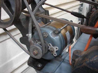
The first thing I tackled was the drive train. The motor on it was not an original, (big surprise) as most of the 70 yr old lathes are that have survived. Typically the motors have been replaced on these older machines which is not a big deal, but what is a big deal is when the original motor pulleys are not re-used. There could be several reasons, mostly because the newer motors have a larger shaft size, or the motor frame is slightly different. If it's a single pulley, it's not a big deal, but if it's a double pulley for a 12 or 16 speed, the original pulley is crucial to mate up to the countershaft pulleys. Unlike the cone pulleys on the spindle and countershaft that use a belt tensioner, the belt that connects the motor to the countershaft relies on the motor placement for tension. Once the motor has been adjusted for the proper tension it is tightened down and forgot about till the belt wears. To change speeds from high range to low range, this is where the FLAT pulleys on the countershaft come in. You simply roll the belt off the flat pulley, and roll it back on the other flat pulley....something you can't do with all V pulleys. And for that fact, the motor pulleys must be of compatible size to use the same length belt on both ranges.
DSC02506.JPG
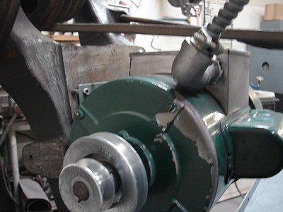
As you can see, this had a single 2" pulley on the motor, which is not original nor close to being correct size even for a single speed. This model calls for a 2-3/32" and 3-13/32" sheeve size. Of coarse the factory pulleys are machined to those specific sizes, not something you'd find on the shelf at the hardware store. After running the numbers through several online belt length calculators, and rummaging through my stash of pulleys, I came up with a combination that worked with a little tweaking. I ended up with a 3" for the big end, and a 1-3/4" that I re-grooved for the small end and it works perfect.
DSC02515.JPG
I ought to mention that I also changed the motor, as the one that was on it was not reversible. I had a slight problem with the connector box interfering with the belt, so I fabbed up a lower profile version to clear. The mounting frame was also slightly off center from the old one , so I had to re-drill the mounting holes in the motor mount.
DSC02521.JPG
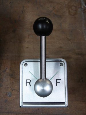
Once that was done, I focused on rebuilding the drum switch. The face had so much wear from switching on and off, that not only was the graphic gone, but the the cover plate was .010" thinner in the wear spots. The contactors had some wear, but not enough to justify a full replacement, so I dressed them off clean and checked with an ohmmeter. There was no saving the faceplate, so I made a new one.
DSC02519.JPG
Now that I actually have a 16 speeds in forward and reverse, looks like the rest is dirty work.
 
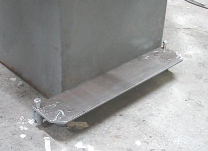
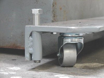
This machine came on a very nice stand that at first I thought was commercial made, but upon closer inspection turned out to be a custom built affair just for this machine. Who ever built it did a bang up job with rolled radius corners and top notch welding. The material is 1/8" thick, and makes the weight about 180 lbs including the drawer. I needed to put this on casters so I could roll it out of the way when I needed more room. I didn't want to raise it much, so I used some 3/8" thick angle iron, inverted to cover the casters and raise it only
about 3/4".
DSC02522.JPG
I added 1/2-13" leveling screws to stabilize the base when it got to where it belonged.
DSC02523.JPG

Now that this is kinda mobile, I can work on it at my leisure without hindering other work.
I tried to contain my excitement by promising myself this would not take over all my spare time, so I was relegated to just "dabbling" with one component or sub-assembly at a time. This made sure I didn't have 4000 parts scattered about, and kept my focus on the component at hand.

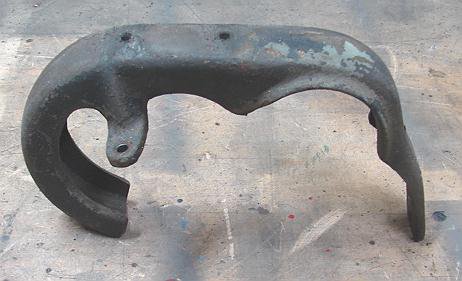
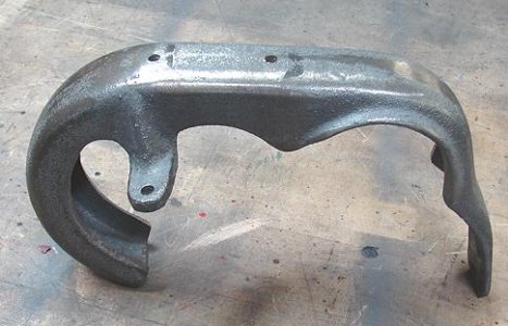
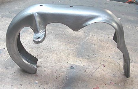
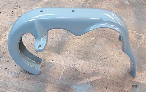
I left off with the drum switch, so I figured I would continue with everything that connected to it. The mounting base for the switch and the backgear cover. The mounting base for the switch was slightly cocked where it was screwed to the gear cover, leaving the switch out of level. After I got the first layer of crud removed, I did some grinding with a die grinder to re-contour the casting for a better fit. The gear cover was the same way....just raw casted parts connected to other raw castings that sometimes do not fit the way they were intended. I wanted a solid fit on both pieces because the switch is mounted to it and it would get a lot of use. So I spent some time fitting castings to each other, getting the most surface contact while maintaining the clearance and position. I could have cheated by using fillers such as JB weld to get a glove fit, but my intention was to powder coat the parts, which means it has to withstand 400 degrees of heat to cure. Fillers such as JB will just fall off. If I had planned to paint it, this thing would be full of filler to smooth things out. Powder coat has many advantages, but the disadvantage is there is more prep work on castings to get a smooth finish.
DSC02541.JPG
As it came off the machine
DSC02542.JPG
After a rough clean up
DSC02543.JPG
After the final fitment and polishing
DSC02544.JPG
Finally powder coated.
Sure, it's a little more work, but a smooth slick surface is lots easier to keep clean, with the benefits of the durability of powder coating over paint.
 
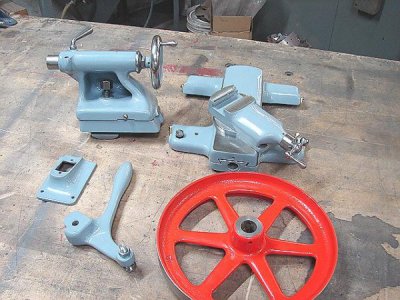
I kept going, getting all of the smaller stuff coated and out of the way. When I got to the saddle, I noticed the crossfeed had lots of slop in the screw and nut. I knew this had to be replaced, but the crossfeed screw is 7/16" -10 LH Acme. This is not a common size by today's standard, so I thought I might try to make one. I wanted to start with the nut first, because I figured it would be the hardest part to make. The hardest part was grinding the threading tool. Once I ground up an internal threading tool, the nut was simple. The screw.....not so much. After 2 attempts, I gave up....there has to be an easier way. Well, there is. I found some 1/2"-10 LH Acme screw stock at McMaster-Carr. 3 ft for $15.00! There was plenty of room to use 1/2" over the 7/16", and the tool I ground up will still work to make the nut. I made a new nut from red brass, and simply cut the screw from the shaft, then drilled and reamed the geared shaft and inserted the new screw and pinned it.
DSC02537.JPG
DSC02538.JPG
DSC02618.JPG
 
Derf, nice work
 
I knew sooner or later I would have to dive into the gearbox and gear train as this was quite noisy when I first fired it up. The gear train leading up to the gearbox was in better shape than I expected, with the usual lion share of the wear being on the feed reversing gears, most of it on the forward gear, because it gets used 90% of the time, and it's always turning. The biggest wear was inside the bore of the gears and the axle it rotates on, mostly the axle. The easiest way to overcome that, is to bore the gears out straight, and make new axles to fit. Then the reverse gear was swapped with the forward gear, as it has less tooth wear.
The stud gear and idler gear were both in great shape, with the wear being on the shafts and bushings. I made a new shaft for the stud gear and an oversize bushing for the idler.
Now to the gearbox.....same deal, all of the wear is on the shafts and the housing they rotate in. Where the gears rode on the shafts had minimal wear. But where the shafts rode in the housing, there's about .015-.020" slop. I wasn't crazy about building completely new shafts, then I realized I didn't have to. The shafts are assembled into the housing from the right side. This means I only have to bush the left side of the casting, the right side can be bored out to accept a pressed on sleeve on the shaft. The shafts are nominal .750" in dia. the full length. I turned the left end to .625" for the length of the wear to clean it up, and it fits into a bronze bushing installed into the housing. On the right end, it was turned to .700" for the length of the wear, then an oversize sleeve was heat shrink fitted. Once the housing was bored out for a full clean up, the sleeve was turned to fit at about .785".
DSC02617.JPG
My gawd did that make a difference in noise! It almost sounds like a new machine! Once in a while in the right gears, I hear a slight ringing coming from the large idler gear, probably end play, but I think a nylon washer will cure that.
 
The gears now run quieter, until I closed the cover. The guard has been sagging over time and now drags on the spindle gear.
dsc02545-jpg.268745

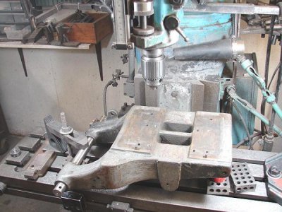
The hinge pin was wobbly, and after inspection it was not any wear on the pin where it goes into the hinge bracket. The wobbliness is because it is not solid in the cover itself. If you look at the pin joint you might notice a large area that looks different that the casting. That's because it is. It's a pour of zinc or tin to secure the pin in the casting.

dsc02546-jpg.268746


I fired up my torch and melted out the mixture, and this is what the pin looks like.

dsc02549-jpg.268747


To re-cast this joint, I first cleaned up the bracket and turned it true to the pin hole.

dsc02548-jpg.268748


I wanted the joint to be as square and tight as I could get it so the pour would not leak out.

dsc02550-jpg.268749


I then ground on the gear cover itself to get it square and fitting the bracket with minimal leakage. To position the cover, I made a tapered sleeve from a piece of pipe to center the gear cover hole to the spindle. Once I got everything in place, I clamped close to the joint.

dsc02552-jpg.268750


When I melted out the pour, I saved it in a soup can, and I'm glad I did. At first glance I thought it was just lead, but after I broke some pieces off, I knew it was a lot harder than lead and did not bend at all. I suspect it is tin or zinc. I remelted with a torch and added a smidget of wheel weight to make up for the small amount that melted and missed the can the first time.

dsc02553-jpg.268751


Now it swings like a new one and doesn't drag on anything. Now I'll dress the top off and nobody will ever know......
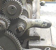
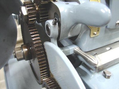
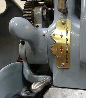
Up to this point, everything I have done is repair or maintainance and I haven't really done any "mods" yet. One thing that I noticed while working on the gear train, was the square head bolt that secures the feed reversing lever. This is slightly annoying to have to open the cover and use a wrench to change feed direction. I know that some of the 9's came with a pull knob type lever, and some with a pinch type lever like found on the 10K's.
DSC02585.JPG That particular wrench didn't come with the machine, nor did I want to buy one, so I came up with a better plan.
DSC02603.JPG
I replaced the square headed bolt with a SHCS, and made an "L" shaped extension that fit over the head and secured with a set screw. I turned a handle from stainless that threaded into the extension. Once the bolt tension and lever position was finalized, it is a simple as pinching the 2 levers together to loosen, then shift and push the lock lever back down.
DSC02604.JPG Since I always get confused, especially with the crossfeed direction, I made a simple brass tag for clarity. Between the lock handle and the tag, I believe it's elegant enough it looks like it always belonged there.
 
Wow! This is beautiful! I remember reading the posts back in May about the gear cover, and thinking I might need to do that. And the use of inverted angle iron for the casters makes me want to get busy on my next lathe stand.
 
Very nice work. Wish i had a teacher showing me these tricks and techniques while i continue rework of my Hendey
 
Back
Top