Boring on the Lathe for (New) Hobby Guys
Being able to bore an accurate hole on the lathe is an important skill every hobby guy should have. We may not need to bore a precision hole all that often but when we need to, we should be able to.
As we all know, that is easier said than done.
I don’t know about you guys but when I started I didn’t really understand how a boring bar actually worked. I certainly didn’t know how to choose them and I didn’t know how to use them because nobody ever told me. Even the manufacturers of our bars had not put out any educational material that covered the basics of boring. Has anybody found the equivalent of “Boring for Dummies” and “How a Boring Bar Actually Works” yet? I haven’t, and I’ve looked hard!
The information I needed was actually out there but it was scattered about in the technical, academic and manufacturer’s literature. Without any other recourse, I decided to sort this boring thing out for myself. Being a little slow, it took a long time for me to tumble onto the idea that if boring bars and inserts have geometries then those features are meant to accommodate or mitigate cutting forces. Duh! It took even longer to figure out how these geometries do that, and then I had to sort out how our usage of those tools augments or modifies their impact on tool performance. Eventually, I developed at least a rudimentary understanding of this process and was then able to bore a stupid hole on size, on purpose and without relying on luck … much.
Sometime in 2005, a mini-lathe guy asked me about which boring bar to buy. This discussion was my answer to him. As you will see, the answer to his question is a little complicated and became what is essentially a Primer, the basic elements, on boring on the lathe. Over the years, I have shared it with some folks and some of them have encouraged me to share it with the HM membership so here it is, rewritten for the final time. You will see references to mini-lathes but since most of the deflection that happens while boring happens to the bar and not the lathe, this stuff should apply to most lathes found in a hobby shop. Just keep in mind that this is MY way of boring on the lathe, not THE way.
I am approaching this subject from the same perspective that I believe the makers of our boring tools use – cutting tool geometry – because, as I hope to show you, it is the only approach that makes sense. As we develop this discussion, keep the following in mind:
The key to boring accurately lies in understanding the cutting forces inherent in the boring process. Then you can see how the different bar and insert geometries alter them and how your usage of those tools refines their effect on these forces. Only then does boring become the simple process it really is.
We will look at cutting forces, basic boring bar and insert geometry and then go through a checklist to show you how it all ties together. I promise, no math!
Let me say up front that I cannot really tell you which boring bar to buy; there are just too many variables that go into that decision and you need to choose a bar based on your own needs. Later on, I will tell you what I use and why.
You will also find that no boring bar does it all and you may as well accept the fact that you will own more than one bar. What I hope to do is give you the information you need to choose those bars wisely because boring bars are potentially one of the most expensive kinds of tooling we encounter. A single (good) carbide boring bar and pack of inserts can retail for almost as much as an entire mini-lathe costs so mistakes here have significant financial consequences.
I should also tell you that nothing qualifies me to write this. I am just a hobby guy like you. The content here is what I have learned over the years, with a perspective that I have not seen anywhere else to date. That doesn’t mean it is correct, complete or anything resembling an authoritative work. Boring is a complicated process with many nuances. In fact, even the nuances have nuances, so I am just going to shoot for the basic elements and you can take it from there.
If you can already bore accurately then just ignore me.
Finally, I have read that boring is just like turning, except it is done on the inside instead of the outside. While I disagree with this statement, the cutting forces encountered with external turning are the same and external turning tool and insert geometries are strikingly similar to that of boring tools. Accordingly, much of the information you find here can also be applied to the use of external inserted carbide turning tools. I hope you find this helpful.
The Force Is with you … like it or not
Anytime a cutter is used in a machining operation there are going to be cutting forces to contend with. Typically, cutting tool geometry is used to counter or alter these forces and boring is no exception. What is not readily evident is how intimately cutting forces relate to the use of a boring tool. Every part of the tool, from the lead angle of the bar to the rake of the insert to the nose radius of the cutter has some impact on cutting forces and we need to understand these forces in order to understand how the tool works and how our work methods impact on the results.
A boring bar is a single point cutting tool that is cutting to one side of a flexing bar deep in a hole where you cannot see. You can imagine that as the tip is pushed into the cut it will be also be pushed down and away as it encounters the rotating mass of the work … as a result, the bar deflects. Let’s look at this more closely.
Deflection is the movement of a structure or structural part as a result of stress, and the key components that stress our boring bar are three cutting forces: Axial or Feed forces, Tangential forces and Radial forces. These forces are ever-present and dynamic whenever the cutter is in contact with the work.
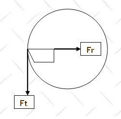
Axial forces run down the axis of the bar as we feed in and do not materially alter deflection. Therefore, anything that alters the other forces toward axial is a good thing.
Tangential forces (Ft) act to push the tip of the cutter down and can actually push the tip below centerline, especially when we have a long overhang. When this occurs the cutter can dig in and the clearance angle under the cutting edge is reduced, causing rubbing, vibration and chatter. This is most critical in small bores where the lower edge of the insert or bar is more likely to contact the work. In terms of magnitude, Tangential forces are the largest of the three.
Radial forces (Fr) tend to push the cutter out of the cut, toward the centerline of the bore. This results in variations in chip thickness as the tip moves toward and away from the centerline, causing inaccuracy, poor finishes, vibration and chatter. Radial forces tend to be the smallest in magnitude but are no less important.
Just to make sure I am crystal clear about these forces, let’s look at them in Bubba terms. If you, Bubba, had a big stick and held onto one end and pushed the tip of the stick straight into a solid wall, the force you’re applying to push the stick are Axial forces. Now, if someone were to grab the far end of that stick and pushed it straight down (while you resisted), that someone is creating Tangential forces on that stick. Now say that same someone stopped pushing down and instead pushed the tip of the stick horizontally, directly away from him/her, again with you resisting. He/she is creating the equivalent of Radial forces.
What your boring bar is seeing is all three of these forces acting on it at the same time, all the time, and the magnitude of each force varies due to multiple factors in real time.
And don’t forget that Bubba is your boring bar holder. Think about the forces being encountered there as he tries to hold onto the end of that stick and keep the tip of it steady while these forces are trying to move the tip of the stick at the other end. Then think about what happens if he lets up on his grip or moves even a tiny little bit …
With that visual, let’s look at the stick.
In addition to these cutting forces, deflection is compounded by bar overhang, bar diameter and the material the bar is made from:
Overhang is the amount the bar is extended from the boring bar holder. It alters deflection exponentially to the 3rd power, such that its impact on deflection at 2” will be 8 times that at 1”. Overhang is dictated by the depth of our bore but it should be no longer than absolutely necessary.
Boring bar diameter influences deflection to the 4th power, such that deflection when using a ¼” diameter bar will be about 5-6 times greater than that of a 3/8” diameter bar. So, a bigger bar is better and more accurate.
The modulus of elasticity of the material the bar is made from also affects deflection. Steel can be extended in a 4:1 ratio (extension:diameter) beyond the holder, while carbide can go up to 8 - 10:1. For example, a 3/8” diameter steel bar would have a maximum overhang capability of 1.5”, while a carbide bar of the same diameter can extend 3.75”. Note that it’s the modulus of elasticity of the bar material that matters and the stiffer carbide bars will trump steel when reach is a concern.
This is why we are always advised to keep overhang to a bare minimum, and use the biggest, stiffest boring bar we can fit in the hole and still clear chips – to minimize deflection.
So, again in Bubba terms, we have the three cutting forces trying to move the tip of the stick and we have Bubba hanging onto the end of the stick, a stick that we now know can move varying degrees under the influence of these forces depending on how fat, how long and how stiff it is. If you have ever wondered if your boring bar was possessed, the answer is no. It is simply dealing with this stuff! And we haven’t even introduced the human factor, the user, into this scenario yet.
Okay, moving on …
Note that Tangential and Radial forces can be calculated mathematically and theoretically accommodated but it assumes the bar is held absolutely rigid, which is not possible. You must also have an NC lathe to input the data; most hobby guys don’t own a NC or CNC lathe. That is not to say you can’t do anything.
Tangential forces can be partially accommodated by setting the tip of the cutter above center height by 0.005-0.010” and then assessing the effect. What you are doing with this setting is anticipating and accommodating the downward movement of the bar brought about by tangential forces because it WILL occur. However, because Tangential forces are affected by a number of factors - the nose radius of the cutter, depth of cut, feed, speed, overhang, boring bar material and the material being cut, the lead angle of the bar and of the insert - it is impossible to tell you that any single setting will work for you. You need to set it to see if the cut is smooth and free with the depth of cut you dial in. The deeper the hole and/or the smaller the bore, the higher we need to set the cutter tip above center height. Get it right and the bar will hiss sweetly as it cuts.
Radial forces can be accommodated by assessing the change in inside diameter (ID) a given depth of cut (DOC) produces. For example, if you dial in a 0.005” DOC and find it produces only 0.0095” change in ID then the impact of Radial forces on your setup is that 0.0005”; adjust your DOC to get the change in ID you need. You may need to dial in a 0.0055” DOC to get a 0.010” change in ID. Doing this to determine a setting for finish cuts is very useful in planning your approach to final size. I know of no other practical way to directly offset the effect of Radial forces but this actually does work rather well.
These adjustments are only a small part of the picture. There are many other things that impact on cutting forces that we will cover later. For now, let’s look at setting up for boring.
Tolerances
As tolerances get tighter the cost in time, materials and equipment goes up. The usual advice is to always ask yourself how tight your tolerances really need to be; why work to thousandths if hundredths will do. This is good advice, but until you are comfortable with boring I suggest you try to work to the tightest tolerances you can for every bore you make so that when you need to bore a truly precise hole it isn’t something you haven’t done before. Practice makes a difference. And besides, it doesn’t take much more effort to bore accurately than it does to bore casually.
You can only cut as accurately as you can measure
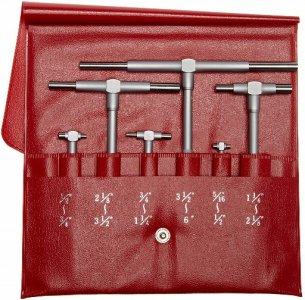
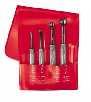
Being able to measure accurately is a cornerstone of machining but it is especially true when boring because boring is a planned approach to a precision result. In order to do that you must be able to measure the bore accurately. There are many devices to measure a bore – bore gauges, internal micrometers, inside micrometers, telescoping and small hole gauges and so on. Telling you how to choose and use all of these tools is beyond the scope of this discussion but for most hobby guys it is my feeling that the “feel tools” – telescoping gauges on the left and small hole gauges on the right– are adequate for most work in a hobby shop. They are capable of reading to tenths if used with care, they’re relatively cheap and are easy to use with a work piece mounted in the lathe.
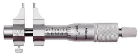
For less precise work I prefer an inside micrometer (shown below) that reads in thousandths; they are fast to use and very accurate.
Regardless of which tool you use to measure bores it is a good idea to have a standard to check your technique and your tool’s accuracy. The standard I prefer to use is a ring gauge. These rings are precision ground, hardened and are often calibrated in tenths; they will be stamped with their ID.
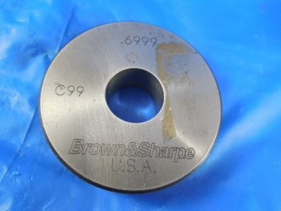
If you can read the bore of a ring gage consistently to tenths with a telescoping gage then you can read any bore to tenths with those gages. The specific size of the ring gage is not important; my mid-sized one is a 0.7514”XX. Buy a smaller one for checking your small bore gages, too.
Another important tool is a micrometer stand or padded vise. It is very difficult to hold a micrometer in one hand, your gage in the other and then turn the knob without something moving. A stand makes this simple. These are available on eBay for very reasonable cost. If you have ever read a telescoping gauge three times and got three different readings then you might want to buy a stand!
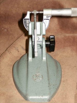
Use your ring gage to find out how your mic likes to read. Lock a telescoping gage in your ring gauge and bring it to the mic and read it. Knowing what the reading should be you can then tell how your mic should be handled. For most mics, you need to turn the spindle of the mic until it just touches your gage, and then take your reading. Just touch; cranking in on a ratchet can move the telescoping gage. Be sure the contact surfaces of the telescoping gage is in the center of the micrometer’s anvil/spindle and the handle of the gage is perpendicular to the spindle of the mic as shown in the picture. This orientation assures you are reading the gage at the widest point.
Setting up the Lathe
Confirm that your lathe is level and that the headstock is aligned with the ways - we don’t want tapering bores unless it’s on purpose. Also check the gibs on your carriage to be sure there is no play. Boring creates a lot of stress on the lathe and any play in the carriage gibs, or even a worn leadscrew or nut, can lead to chatter in the bore. If you lock your carriage when boring then be sure to set your cutter center height with the lock engaged. Also be sure there are no burrs on your carriage top or compound that can allow a tool post to spin under load.
A depth stop is useful when boring to precise depths or when cutting a flat bottom. They are simple to make for most lathes. On my Sherline lathe I use either a stop screw or a micrometer head, depending on the situation. I typically bring the stop into contact with the carriage after I feed in to final depth (before I start boring); then I zero the hand wheel. While boring I use the stop to tell me when I am close to the bottom and use the zero on the wheel to stop precisely. The stop is a reference, not a solid stop. A DRO or even a piece of masking tape on the ways will serve the same purpose.
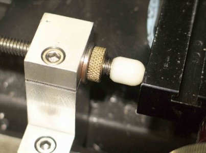
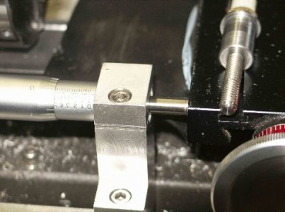
On my larger Emco lathe, I have a very robust and solid carriage stop. The stop is locked at the final depth of the bore and I put a mark with a Sharpie on the boring bar about ¼” before I hit the stop. I use power feed to get to that mark, disengage the feed and manually move the carriage into contact with the stop. Then I move the cutter away from the wall and retract the bar before making the next cut. My lathe has a clutch at the end of the feed shaft so I could just use power feed all the way and bang into the stop and then turn the power feed off but that seems too much like an assault by a newbie so I don’t use it that way.
Your boring bar holder is VERY important.
Most of us use a Quick Change Tool Post on our lathes but the boring bar holder that comes with these posts typically locks directly down on the boring bar with 3 or 4 set screws. This is the least secure way to hold a boring bar. It is also guaranteed to mar your expensive carbide bars and can even break them. These holders can be a source of chatter – I suggest you buy or make your own.
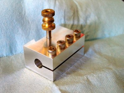
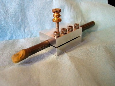
The holder above was made for my Sherline lathe. It completely encases the boring bar in a finely finished bore and holds it very rigidly. 6061 T-6 Aluminum is fine for bars up to 3/8” diameter; for larger bars, use steel.
The length of a holder should be at least four times the diameter of the bar. This holder is just long enough to fit a 3/8” diameter carbide bar at full extension (4” hanging out); for a 6” long bar this amounts to just over 2” that can be held so this one is 2.125” long. The dovetail is made first. The 10-32 locking screw holes are drilled for a roll tap, and then the hole in the center of the 1-3/8” wide x 1” thick body is drilled, bored and reamed to a fine finish before the compression slot is cut. Then the upper screw holes are drilled to clearance diameter and the bottom half is tapped. In use, just snugging the screws is enough to hold the bar solidly. A QCTP using this holder can handle a 3/8” carbide bar at full extension making deep cuts but I would not trust the typical tool post found on most mini-lathes to handle a larger bar unless you brace it. Mini-lathe guys, you want to make this holder.
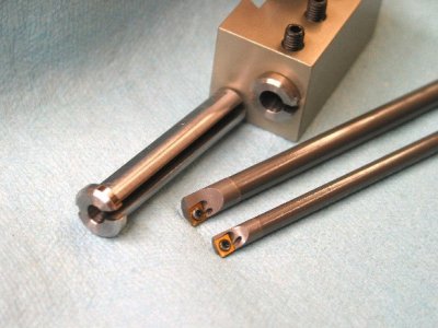
Sleeves can be used to hold smaller bars (1/4” and 3/16” bars shown). These sleeves are made of mild steel and have a compression slot on one side and a shallow expansion slot on the other. Length matches the holder and the hole to receive the bar is reamed carefully. These sleeves fit the shop-made holder shown above. A flat is machined on top of the sleeve to also allow use in the standard QCTP holder.
If you’re using a larger lathe and have a solid Aloris-style quick change tool post then a standard tool holder that surrounds and clamps the bar will work fine. An example of this type of holder would be the Aloris 4D shown below; the AXA version works fine for bars up to ¾”.
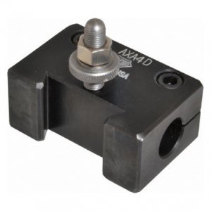
Unlike import boring bar holders that use a cotter arrangement to put pressure on the bar in just a few places or that uses set screws that bear directly on the bar itself, the 4D uses screws that compress the entire length of the tool holder to firmly and evenly grab the bar. It also allows you to fully compress adapter sleeves for smaller bars and hold them very rigidly. In my opinion, this is a superior tool holding design.
Regardless of the tool holder you use, keep in mind that the holder should be at least 3 - 4 X the diameter of the bar to assure rigidity based on the Lever Rule. The Aloris AXA-4D is intended to hold a ¾” OD bar and is 3” long; this length is not a coincidence. This recommendation comes from Dr. Uwe Heinrich of Micro 100. See his article that I am attaching: Cutting Tool Engineering, December 2005, Volume 57, Number 12, “Stable Environment”.
Part two
Boring Bars
There are two basic kinds of commercial boring bars – solid bars and inserted tip bars - and many other kinds of commercial bars, shop-made bars or between-centers bars. We’ll only look at the commercial bars commonly found in the typical hobby shop because I can’t possibly cover them all.
Non-interchangeable tip/solid bars
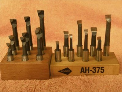
The ubiquitous Chinese brazed carbide steel-shank boring bar set on the left and a high quality Borite solid M42 HSS Cobalt boring bar set. Both have 3/8” shanks and are the zero lead type of bar.
The sets shown above are typical of this type of bar. These are available as brazed carbide, solid carbide, HSS and cobalt HSS. As you can see, they include bar sizes from small to large that can bore shallow to deep, and will fit both a lathe bar holder or a boring head on the mill. Their tapered bars reduce resonance on this type of tool and their shank diameters appropriately increase as they lengthen. These bars typically have no axial or radial rake and have little to no nose radius from the factory.

This diagram from Criterion depicts the different lead angles solid bars can have. The positive and zero lead bars can bore to a shoulder while the negative lead is for through holes only. Positive lead bars focus the cutting forces at the tip and shift radial forces toward axial. They also clean up the bottom of the bore better. Zero lead bars tend to alter radial forces toward axial also and cut with less chatter. Negative lead bars finish well and are stronger.
Most “sets” come with zero-lead bars. If you have a surface grinder, you can grind a 5 degree positive lead on the tips of these zero-lead bars and they will work better for lathe boring. This works especially well if you do a lot of closed bottom bores. You can also buy sets with a 5 degree lead angle already on them but they are not as commonly available.
These bars are typically mounted with zero radial rake (the top of the cutting tip is horizontal to the bed when viewed from the tip) and typically square to the bore (the center of the shank parallels the ways). However, since the clearance profiles under the edge are typically rounded, this allows some latitude in creating some positive radial rake by turning the tool in the holder so the cutting tip points up slightly; this lowers tangential cutting forces at the edge. You can also angle the tool along its axis (turn the tip toward the wall of the bore) a few degrees at the same time to further reduce radial cutting forces at the very tip; this reduces deflection from radial forces by decreasing the amount of side cutting edge engaged in the cut. There are limits to these maneuvers but used in small amounts the tool will cut with greater ease and accuracy. Give it a try.
Depth of cut and feed rates are not specified with these bars. When used on the mini-lathe I typically rough at around 0.010” to 0.015” and finish at 0.001 – 0.005” for the cobalt set and 0.020/0.005” for the Chinese set. This seems to work fine for me. I use speeds that are generally about 2/3 typical turning speeds for HSS because of the thinner profile of the tapered shanks but you will need to try it and adjust to produce the chip you want. In aluminum, brass, plastics and mild steels you can run at normal turning speeds or even faster with the shorter bars.
Personally, I rarely use this type of bar on my lathe anymore. They are mostly relegated for use in the boring head on my mill where they excel and I pretty much only use inserted carbide tooling for lathe boring. If you prefer this type of bar then I suggest spending some money on individual bars or a good set from a reputable maker (Borite, Bokum, Circle Machine/Widia, Criterion, Micro 100 are some good ones). There are many different configurations available from these makers and I can attest that they work exceedingly well … at a cost.
If you regularly bore small diameter holes then I suggest solid carbide bars from Micro 100. Their tiny boring bars are excellent and their higher modulus of elasticity allows them to bore quite deep for their diameters. For bores below about 3/16”, these are pretty much all I use. They also make bars for internal grooving, thread relief and threading and I can highly recommend all of them. They are very simple to sharpen by honing the flat top on a fine or extra-fine diamond stone and they will last for decades when cared for.
Inserted tip bars, aka Indexable tip bars
In my opinion, an inserted tip boring bar is the most useful type of bar for most hobby shops, primarily because their constant diameters allow us to use only enough of the bar’s length to suit the bore depth. Moreover, inserts usually cut consistently until the insert wears. This is a major advantage because boring is a game of predictable accuracy; inserted bars, and especially those with solid carbide shanks, give you that … if you know how to use them.
The obvious caveat is that you need to choose the right bar and insert for the job and it can be really confusing when choosing one. You can go to most industrial supply houses to see checklists like the one below; they are intended to assist you in choosing a bar but lack the details you need to really make an informed choice.
I’m going to fill in the blanks so the items on the list make sense. I’ll also add a few things to the list that they don’t include but know that the best source of detailed information on a particular bar is the manufacturer’s product description; download their brochure that pertains to the bar/insert you are considering.
Step 1: Determine hole size to be bored. Proper bar selection will have largest minimum bore dimension under hole size to be bored.
Step 2: Determine bore depth or how far boring bar will extend out of holder. Multiply bar diameter times 4. If bore depth is less, use a steel bar; if bore depth exceeds 4:1 ratio, use a solid carbide bar.
Step 3: Determine shank size needed.
Step 4: Determine if the machining application requires a boring bar with a 5° front lead angle or with a 0° lead angle. Also, if a left handed bar may be applicable.
Step 5: Select Boring Bar.
Step 6: Select insert geometry to fit boring bar.
Step 7: Select desired corner radius needed for particular machining application.
Step 8: Determine materials to be machined.
Step 9: Refer to carbide grade selection chart below.
Step 10: Select proper insert, corner radius and grade.
Let’s discuss this in more detail:
Determine hole size to be bored. Proper bar selection will have largest minimum bore dimension under hole size to be bored.
The manufacturer assumes that we would drill a starter hole that is within ~0.030” – 0.050” of the finished bore diameter, then finish bore the hole to size with a bar presumably bought for just that purpose. Basically, they are asking you to choose the biggest bar that will fit in the starter hole and still be able to clear chips.
Depending on the bore size, this one can catch you out if you aren’t careful. For example, say you need to bore a ½” precision bore. You would think that a 3/8” diameter boring bar would work, right? The minimum bore is around 0.421” for this type of bar so if you drilled a 27/64” hole the bar should fit. This theoretically leaves you with a whole 0.0395” of wall thickness to work with but since drills do not leave straight, clean holes we need to take a cleanup pass. If your insert has a 0.007”NR then we need to take an additional 0.005 – 0.010” depth of cut on top of that 0.007” (more on this later) for a chatter-free cleanup pass so, at minimum, we need to take a 0.012” deep pass. This leaves us with a wall thickness of 0.0155”. You now have two options. First, you can try taking a 0.00775” deep pass if you think you can dial it in or second, you can try taking two finish passes of 0.0038” and 0.0039” and hope you nail the bore. As we’ll see further along, the latter is probably the best option provided you can dial in a cut in tenths of an inch.
Personally, I would prefer to use a 5/16” bar and have much more room to approach the final bore. A smaller bar may allow me the option of using an insert with a smaller nose radius, say 0.002”. This gives me far more control over the cut by minimizing the effect of radial forces enabled by the smaller nose radius. This will make more sense later on but for now accept the point that bar selection requires us to consider not only the bar diameter but the insert nose radii the bar will accept because that determines how deep we can accurately cut. Yup, there is more to it than just what will fit in the hole. Sometimes smaller is better if it allows you to go deep enough, gives you more room to work and clears chips easier.
Chip clearance is very important. The bar has to fit into the starter hole and have room to get the chips out. If the hole packs with chips they will get between the work and the cutter tip and impair your accuracy and finish – a lot. If they pack up enough they may even prevent you from reaching the bottom of the bore until you clear them. When the manufacturer lists a minimum bore size, what is unspoken is that this assumes you are using a depth of cut and feed rate that produces coiled chips that clear readily, not long stringy chips that can pack up in a bore.
How deep do you need to bore? This will determine the shank size of the bar and the material it is made from. The deeper the bore, the larger your bar’s diameter should be; and if the required bar extension is beyond a 4:1 depth to diameter ratio then you are looking at a carbide bar.
So, you have to be asking yourself just how rigid this 4:1 (for a steel bar) recommendation really is. Can you exceed it, and if so then by how much? I tested my steel bars and I suspect your results will vary because we are using different bars and inserts but what I found is that I can get to almost 5:1 before I start seeing inconsistencies in how the carbide inserts cut. For me, that 4:1 is pretty close and I suggest you test your own bars to see how limited you really are.
Steel bars are fine for shallow bores but over the years I’ve found that if I opt for a steel bar to contain costs I will later buy a carbide bar of the same diameter to go deeper and that steel bar will sit in a drawer. Consequently, I have learned to only buy carbide bars because I can own fewer bars and cover more range. In the long run, it’s cheaper.
There are some bars made of Tungsten that is halfway between steel and carbide, both in stiffness (extension capability is 6:1) and cost. They are meant to be more economical than carbide while giving you a bit more depth capacity than steel. These are not commonly found in the home shop. Some bars even have an internal damping feature; typically they are steel with a rubber mounted tungsten insert in the shank to reduce resonance. I have no experience with these but mention it here for completeness.
What is the insert clearance angle? Another factor that is related to bar diameter, especially for small bores, is the clearance or relief angle under the edge of the insert.

An 11 degree insert works well in bores down to about 0.20” ID; this much relief angle is usually only found on inserts for smaller bars up to around 5/16”. This will give you more space as tangential forces push the cutter down. For bars above 5/16” diameter that have greater inherent stiffness this clearance thing becomes less of an issue. Inserts intended for larger bores will often have relief angles of 5-7°. Inserts for negative rake bars often have relief angles of zero; the bar itself beds the insert at a downward angle, thereby providing the needed edge relief.
The relief angle is usually tied to the nose radius. Most inserts with a 0.002-0.004” nose radius will automatically come with an 11° relief angle on it but you should check. As the nose radius gets bigger, the relief angle typically decreases.
What kind of bar lead angle do you want? There are two common types of bar geometry or lead angle on inserted tip boring bars: positive (typically 5-7°) and zero. Both can bore to a flat bottom, a shoulder or a through hole, and both also work on a small lathe. These also come in right and left hand but unless you plan on boring with the lathe in reverse, choose a right hand bar.
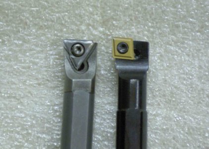
Zero lead on the left, positive lead on the right. Note the positive lead insert is canted with a 5 degree tilt so that the point leads the way. The zero lead insert has the leading edge square with the front of the bar. Note that the tip of the insert just clears the side of the zero lead bar; it is very well supported so strength is enhanced.
Positive lead bars help alter force vectors from radial to axial based on the geometry alone. It holds a diamond-shaped insert at an angle that cleans up the bottom of the bore better because only the point cuts as you feed toward the centerline. These bars are better for blind bores. The inserts have only two usable tips but if used properly the inserts last for quite some time in a hobby shop.
The main advantage of a zero lead bar is that when used with a DOC (depth of cut) greater than the Nose Radius most of the cutting force is axial so it is less likely to chatter with heavier cuts, which really helps accuracy. This bar does not clean up the bottom of a bore well – it rubs across the leading edge – but it excels for through-cuts. The insert is supported very well so the inserts for zero-rake bars tend to last longer. Trust me; a good zero lead bar with a good operator behind it can bore really, really accurate holes.
So, which one to choose? I don’t know about you but the vast majority of the bores I make are closed bottom bores so I most often use a positive-lead bar because it cuts without rubbing; the geometry also reduces radial forces, a big plus when accuracy is critical. I also use a zero-lead bar, primarily for through holes or when I need to do a lot of roughing. For me, this is not an either/or; I own both types of bar geometry and use them for different scenarios but if I could only have one, I would choose the positive lead bar.
Stuff to consider regarding insert rake angles.
I want to lead off by telling you about a positive axial rake insert that reduces tangential forces at the tip. It also helps reduce the incidence of a BUE (built up edge) in softer materials.
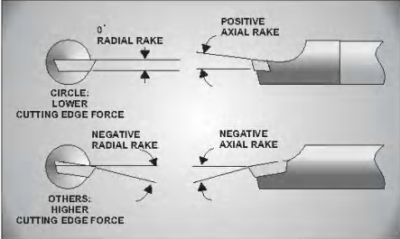
This illustration is from Circle Machine and clarifies the different rake angles.
Circle Machine offers bars (the CCBI series) that uses flat topped inserts that have a positive axial rake and zero radial rake (see illustration above). In my experience, they cut more accurately, feed easier and finish better than a zero axial rake insert; on a manual feed lathe you can definitely feel that they cut with less resistance and the chips literally fly out of the bore. From a geometry standpoint I believe positive axial rake acts like back rake on a turning tool; therefore, it should focus the cutting forces at the leading edge of the insert while also thinning the chip and accelerating chip flow. Now, if the bar itself also has positive lead geometry then only the very tip of the insert engages the material, not the entire leading edge.
This is an ingenious design. You have the positive-lead bar geometry creating a large axial component (lower radial forces) and the positive axial rake insert reducing tangential forces and boosting chip clearance … a LOT. These features make this bar design ideal for use on smaller lathes and/or smaller bores, which is probably why positive axial rake inserts are usually found only on smaller boring bars (3/16” to 5/16”).
This geometry is very accurate. The inserts for these bars come with nose radii down to 0.002”. What this allows the bar to do is take very small cuts without radial forces deflecting the bar much at all. A 0.003” depth of cut is already 1.5 times the nose radius and this insert will cut that depth, time after time. It will also take a 0.001” finishing depth of cut and is actually pretty accurate when doing so. This is a really useful capability when tolerances are tight or when you just have that smidgeon more to take off.
This seems like a lot of discussion about a little geometry thing that I would guess 99.9% of hobby guys are unaware of. And it really only applies to smaller bars, from 3/16” to 5/16” diameters. So what’s the deal, Mikey? Well, I just told you about the most accurate carbide boring bar and insert geometry that I am aware of. Given that a large proportion of bores that are done in a hobby shop will be within the reach of these bars, I thought it important to make you aware of them. A boring bar is not limited by bore diameter, but by bore depth. Just about any hole that is 2-3” deep or less can use these carbide shanked bars so keep them in mind when you need a precision hole.
Okay, moving on …
A zero axial rake insert is found on the vast majority of boring bars and cuts well, though it does so with greater tangential forces than a positive axial rake cutter. This can be offset by raising the bar above the lathe centerline so don’t avoid a bar because it has a zero axial rake insert. In addition, many inserts used on boring bars are called “positive rake” inserts and have their own unique upper surface topography. You will need to evaluate this on an individual basis because there are just too many of them to discuss here.
Negative rake tools (like bars that use Trigon inserts) bed the insert so the tip has both negative axial and radial rake. They cut with much higher tangential, radial and axial cutting forces – you will feel this in the higher resistance to feed when compared to a zero radial rake bar. The inserts tend to be much stronger since the tip is well supported; accordingly, they are most commonly used in production situations. They rough well and finish nicely but deflection can make holding tight tolerances a challenge, at least in my hands. I’ve have only owned three of these bars so I don’t have extensive experience with them but I personally avoid negative rake bars. I also avoid zero rake bars that have a tool orienting flat on top that forces the bar to have a negative approach angle (tip pointing down).
When choosing inserts pay attention to the carbide grade of the inserts that are available for the bar you’re considering.
There are many grades available, each with coatings and characteristics that may make one more suitable for a particular material than others. You are advised to consider inserts in light of the geometry and nose radius you prefer and then consider whether a particular coating or grade is preferable for the material you plan to bore. Typically, the maker will also tell you which ones are suited for general work.
Now, with that said …
Circle Machine lists 26 grades. Of these, I have CG5, CG6, CM1, and TN7 grades. I will be very honest with you and say that I cannot tell much of a difference between them. I tested them against each other for finish, wear resistance and consistency of cut. I used stainless steel, semi-hardened steel, mild steel, aluminum and brass for these tests. I even drilled a cross-hole across the bore to simulate interrupted cutting. While there may have been small differences that I could not measure or detect, I basically found little performance difference between these inserts.
I am absolutely sure a turning center doing production runs will show an advantage for one over the others but on a hobby lathe that bores all sorts of non-production or one-off projects in multiple materials at relatively low speeds (3000 RPM max) I see little to suggest one grade is much better than the others. If I find one of these grades with the nose radius I want at a fair price then I buy them with confidence. Your experience and pocketbook may vary.
If you work with a lot of aluminum then inserts with a TiC or Al2O3 coating are said to have anti-welding properties that may help to reduce the incidence of a built up edge (BUE). I have not confirmed this myself … yet.
With regard to insert geometry, they are referring to the shape of the insert – diamond, triangular, etc. You will find that most zero lead bars and negative rake bars use triangular inserts, while most positive lead bars use diamond shaped inserts. Personally, I tend not to choose bars based on insert geometry/shape because it tells me nothing. I choose based on the bar lead angle that I need, the nose radius available on the inserts I am interested in and whether or not I can find a flat topped insert for that bar. Others have their own opinions, I’m sure.
I should mention one very popular geometry, the CCGT AK inserts intended for use with aluminum. These inserts are ground to a sharp edge and are uncoated. They have a very positive rake geometry that improves chip flow and reduces the incidence of a BUE in aluminum. Although they are intended for aluminum they work with harder materials, too, although the edge won’t hold up as well. It puts an excellent finish on stainless steel and brass. If you bore with an SCLCR bar you probably already know about this insert. If not, give them a try.
Chipbreakers
The vast majority of boring bars use inserts with chip breakers … but not all. You would think that a chip breaker is a critical feature for a boring bar insert, especially since most inserts have them. However, when boring, chip formation and chip clearance is more a function of DOC and feed.
Feed too slow and you get a nest of stringy tangled chips, regardless of the presence or absence of a chip breaker. Feed at the right rate and you get coiled chips that readily eject from the bore, chip breaker or no chip breaker. Take too light a depth of cut and you’ll get strings in most materials, chip breaker or no. The presence or absence of coolant or cutting oil also impacts on chip formation and clearance. Cutting oil, all by itself, can turn stringy chips into coiled ones that clear readily, chip breaker or no.
I’m sure there are good reasons to have chip breakers on boring inserts used in high speed machines. My problem is that I don’t own one of those machines. What I’ve found is that chip breaker inserts usually require a relatively heavy cut for the chip breaker to work properly, and that can be problematic for a small bar to handle in harder materials. This heavier cut also requires a faster feed rate so power feed would be recommended, which is fine in a through bore but may not be a good idea in a shallow blind bore.
This has led me to avoid chip breaker-type inserts for my bars if I can. I prefer flat topped inserts with no chip breaker, although I admit they are harder to find and therefore can be more expensive. In my experience, they cut with lower cutting forces and work well with much lighter depths of cut. They are also the most rigid of the available edge configurations and are ground to a sharp edge. Moreover, with the right feed, even with a light depth of cut, I get coiled chips that eject readily from the bore, coolant or no coolant.
All the Circle Machine carbide bars that do most of the work in my shop can use flat-topped inserts and I chose Circle Machine specifically because of their intelligent approach to bar and insert geometry. Of all the bars I have owned and used, well over 20 inserted carbide bars at this point, these bars are easily the most accurate and I believe the insert has a lot to do with that.
I am not saying to avoid bars that use inserts with chip breakers. I’m saying that if you have a chance to bore a hole with a flat top insert, try it and make up your own mind.
The insert’s Nose Radius (NR) is the single most important feature to consider when choosing inserts. The impact of the nose radius on boring bar performance is significant, perhaps more so than any other feature in your boring set up aside from your bar holder.
Inserts are available in a wide range of nose radii. In general, the most useful NR is 0.007-0.008” for general work, while a 0.002” – 0.004” NR works well for very small bores or tight tolerance work. I have tried but no longer use a 0.015” NR cutter due to the relatively heavy cuts it required; they also deflect too much to be useful to me for precision boring.
NR effect on cutting forces:
The bigger the NR the greater the tangential forces will be so a smaller NR is preferable for smaller bars used in smaller holes where running out of insert clearance angle is a concern. Smaller NR inserts do limit finishes, however, so increasing speeds and slowing feeds may be necessary.
NR effect on radial forces depends on the depth of cut. If the DOC is less than the NR then radial forces increase with DOC until it exceeds the NR, at which point radial forces are determined by the lead angle of the bar. For example, if you have an insert with a 0.007” NR, then any depth of cut less than 0.007” will be less consistent and has more potential for chatter. However, once the depth of cut exceeds the nose radius by even a few thou the insert is very stable and will tend to cut consistently.
This also implies that a zero lead bar will cut with lower radial forces than a positive lead bar when DOC>NR. In practice, however, I have not noticed a major difference in accuracy with either bar geometry provided the depth of cut exceeds the NR.
This depth of cut thing also explains why a finish cut that uses a DOC<NR often produces a variable change in ID; radial forces are higher so we must determine what the impact of those forces is in a trial and either accommodate it or, if it is consistent, use it.
Radial cutting force is a real thing, as is the deflection it causes. If you have tried to come in on size by taking tiny cuts with an insert then you’ve already discovered that it doesn’t work well. Sometimes it cuts, sometimes it doesn’t cut and then it suddenly cuts too deep! Radial forces are the reason why.
NR greatly affects your cutting conditions (feed, speed and depth of cut are collectively called your cutting conditions).
Recommendations for setting your roughing depth of cut vary by the manufacturer. They will list the recommended DOC, feeds and speeds for the insert when used with all common materials on the box the inserts came in or in their literature. Note that the manufacturer will not usually give you different DOC settings for roughing and finishing; they only give you one recommended DOC.
Practically speaking, the best general recommendation I have seen comes from Criterion, a leader in the boring bar/boring head industry, who recommends NR+ 0.005-0.010” for a roughing DOC; this provides better support at the tip to reduce chatter and works with all the inserts I own.
Note that the recommendations for roughing cuts are not huge cuts, even from the manufacturer. Instead, they are usually just deep enough to bury the nose radius in the cut. This stabilizes the insert to minimize deflection, reduce chatter and improve accuracy. You can go deeper but then tangential forces rise; everything is a tradeoff.
For setting a finishing DOC, things are less clear but in no case should you use a DOC less than 1/3 NR. Again, the reason for this is that radial cutting forces become too large at very small DOC. A general guideline is to use a DOC no less than about 1/3-1/2 NR to finish.
Note that a “finish” cut is not so much about the actual finish, although that is important. A finish cut is about coming in on size after you rough out the bore so we’re really talking about accuracy. When we take cuts smaller than the NR, radial forces are very high and you will notice that what you dial in is not what you get, but what you get will tend to be consistent if you adhere to this 1/3-1/2NR thing. The reason is pretty simple. Within this range, the nose radius is just deep enough to bite but not enough of it is engaged to push the nose of the cutter out of the cut excessively. As more of the nose is engaged beyond about 1/2NR, radial forces rise. As less of the cutter is engaged below ~1/3NR, the nose tends to skip or skate and will not cut. That 1/3-1/2NR range is just about right. The reason that it matters is this will be the minimum depth of cut the cutter will reliably take. You have to confirm it with your insert but it will be close to this range.
If you’re wondering why the heck we shouldn’t rough with less than the NR but we can finish with a cut less than the NR, the reason is that our feed is usually reduced with a finish cut (see the next bullet below) so axial and tangential forces are proportionally reduced. I know, it’s confusing but try it and see. A cut with 1/2NR DOC taken at roughing feeds may chatter but the same cut at a slower finishing feed won’t. Yeah, weird.
You will find that the most accurate cuts will be larger than the NR, which is why having a bar that can accept inserts with small nose radii is really important when you need a precision bore. For example, a 1/2NR depth of cut with a 0.008”NR insert amounts to 0.004”, which is double the NR of a 0.002” NR insert. Clearly, if your bar can take both nose radii, switching to the smaller one when you’re close to your finishing passes is not a bad idea.
Regardless of which insert you use, you have to run trials with your inserts to determine how light a cut you can take and still produce consistent results. This is really important to do, and you must do it for every insert and bar you own.
Once you find reliable settings, write down the bar, insert designation, the size of the NR, the DOC that works for both roughing and finishing, speeds, feeds and type of coolant used. These settings may vary with the material being cut so note any differences if this is so. Keep this valuable information somewhere accessible. One day, you will be 0.006” away from final size and you will know how to cut it.
Feed rates are also closely tied to the NR. A general guideline is that a feed rate of about 50% NR, in inches per revolution (IPR), works for roughing and about 25% NR works for finishing. Much depends on the horsepower of the lathe, DOC, material being cut, and overhang. In no case do we want to exceed the NR when feeding.
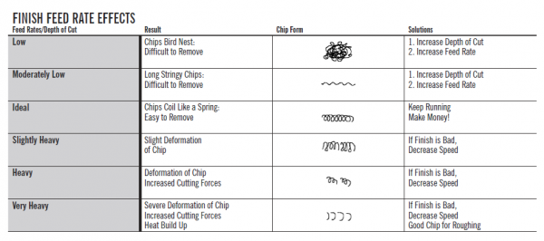
Most folks tend to feed too slow when boring, thereby producing long stringy chips that plug up the bore instead of ejecting out of the bore as they should. Ideally, you are looking for a feed that produces chips that looks like a coiled spring; if you see that, you’ve got it right and the feed will be faster than you expect. If you calculate a feed rate and it produces stringy chips, just increase the feed rate and ignore the calculations.
Quite often, us hobby guys get hung up on precision this or precision that. Lathe work teaches us that we need to respond to the cut and this especially applies to boring. You can set a reasonable speed and depth of cut but it is also perfectly acceptable to use a manual feed to produce the chip shape you want; you are not tied to the feed your gearing mandates. Just an opinion.
What about speeds? I suggest using the recommendations from the manufacturer of your boring bar insert. They will have the SFM listings for all common materials and you can calculate your RPM, then adjust feed according to how your chip form turns out. Studies suggest the correct speed is more important in prolonging insert life than feed rates but in my hobby shop on a manual lathe this may be a moot point, especially in softer materials, because the proper speed is often well above what my lathe can produce. Hence, I try for the best speed and feed to get the chip shape I want and I often vary both to get the results I want.
I also find the following table from Parlec a useful guide:
Okay, I hope that covers the list. There should be enough information here to help you to sort through the manufacturer’s listings and decide on what you need.
It should now be evident why paying attention to cutting forces matters. Just about everything we think about when choosing and using a boring bar is influenced by these forces. Try to keep in mind that sometimes smaller is better and this applies to both the bar diameter and the nose radius you choose. You are also going to find that if you need to do precision work then you need to invest in good tools.
The Bars I Use
These are the bars I currently use the most. They allow me to bore from about ¼” ID out to as large as my chucks can hold, and from shallow to about 6.25” deep. So far, this has been enough for me.
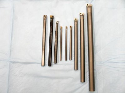
From Left to Right:
- 3/8” Kennametal carbide zero lead bar with a hex shank, chip breaker insert with 0.008” NR. This is my through-hole-hogger and it will flat out remove metal but it does so with consistent accuracy. Inserts last forever on this bar. It has a hex shank and I suspect this is why I can feel everything when it cuts.
- 3/8” Kennametal steel positive lead bar with a hex shank and 0.008” NR chip breaker insert. Used mainly for shallower blind bores in stainless steel because I like the tactile feedback I get from this bar in that material.
- 3/8” AR Warner steel zero lead bar with a hex shank that uses a HSS insert, 0.008”NR. I tend to use this when I need a critically accurate cut in aluminum; the HSS inserts will usually cut what I dial in with that material. It works well with stainless steel, too. Inserts are easily sharpened and re-used; my current insert has lasted over 10 years at this writing and cuts like new. I once broke all the rules and bored a 30mm ID X 4” deep hole with this bar and got an air bearing fit in aluminum. Trust me; this is a good steel bar.
- 3/16” Circle Machine CCMI positive lead carbide bar that takes grooving and threading inserts. A specialty bar that allows me to cut a thread relief and then thread a ¼” or larger Class 3b hole almost 2” deep. Coupled with the two CCBI bars below, it gives me the same capabilities as the three QCMI bars below that.
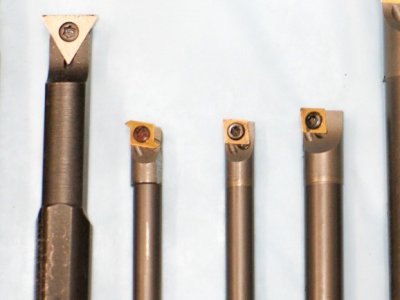
- 3/16” and ¼” Circle Machine CCBI positive lead carbide boring bars that take both 0.007”NR and 0.002” NR flat topped inserts. These 4” long bars are the most accurate bars in my shop and give the best tactile feel of all my bars. Both use positive axial rake inserts that literally shoot coiled chips out of the bore. Although they are available, I do not use chip breaker inserts on these bars. These bars will usually take a 0.001” DOC when I use a 0.002”NR insert in most materials … very useful.
- 3/8”, ½” and 5/8” Circle Machine QCMI positive lead carbide bars that use 0.007” NR flat topped or chip breaker boring inserts. Each one also accepts grooving and threading inserts so they can bore a hole, cut a groove or thread relief at the bottom and then cut a thread all the way down the bore with great accuracy. All bars use the same inserts. These bars cut silky-smooth and chatter-free and are the most accurate larger bars I’ve used, even when compared to other top tier boring bars. Each one will take a 0.004” DOC with a 0.007” NR insert in most materials and cuts consistently.
If I were going to set up my hobby shop today and had to choose a good combination of bars for general use, I would choose these three Circle Machine bars:
- ¼”: CCBI-250-4-5R
- 3/8”: QCMI-375-6-5R
- ½”: QCMI-500-8-5R
It should be clear that no single bar will do it all. Most of us accept that we will eventually need multiple bars. Some of this is repetitious, on purpose:
- Please don’t saddle yourself with a set of bars with a bar and insert geometry chosen by some unknown guy unless it is exactly what you need.
- Before buying the bar, make sure the inserts and nose radii you want to use are available to fit it. Pay very close attention to the nose radius you choose because when boring, this matters a LOT. Again, for general work, a NR of 0.007-0.008” is most useful. For smaller bars, the ability to use an insert with a 0.002” to 0.004” NR is really important, especially if accuracy is critical for you. I highly recommend you use good inserts and download the catalog of your bar maker to be very sure you know which inserts to use for your application. The bar is important but the insert is more important; pick the right one.
- Be sure the bar is long enough to be used at the full extension the bar material is capable of while also allowing enough length to be held in the tool holder. For example, a ½” carbide bar can be extended about 5” beyond the holder; you also need about 3” to go inside the holder, so the bar must be at least 8” long.
- To save money in the long run, please try to buy carbide bars. Steel bars work, no doubt, but you can bet you will buy a carbide bar of the same diameter at some point and that steel bar will sit in a drawer. Why? Because you will someday be limited by the bore size you need but it will be deeper than that steel bar can reliably reach. If it is a precision bore that must have a consistent diameter all the way down the bore then carbide is your best bet. You’ll buy that carbide bar and that steel bar will sit, you’ll see.
Bottom line: Carbide bars simply allow you to do more with fewer bars, do it more accurately and ultimately for less money. And you’ll have more drawer space!
Far and away, the cheapest place to buy boring tools is eBay. If you know what you want and are patient, you will eventually find what you need at a fraction of their retail prices.
Putting it all together
Choosing a bar/insert combination is just half of the equation. The way we use the bar is the other half and it is arguably the more important half. Rather than just a tips and tricks approach, I have chosen to use a boring checklist that the newer guy may find more useful. I’ll throw tips in where they seem applicable. Cutting conditions may be specific to your insert; check the box the inserts came in or the maker’s catalog.
- Do all your calculations first – your anticipated initial roughing and finishing DOC and feed rates. If you already know the optimal depth of cuts your bars can take then you’re way ahead. Speeds and feeds are usually on the back of the box your inserts came in. Don’t get married to these calculations. You will need to adjust to the cut as you bore; this especially applies to feeds.
speed and alter feed to give you the chip shape you need.
- Know your final ID, tolerances and finish requirements if there are any. I always bore to the tightest tolerances I can. It takes me no longer to be careful than it would to be sloppy.
- Zero your mic and place it in a stand or padded vise. Lay out your hand tools. I always do some trial runs with my telescoping gauge and ring gauge to be sure my technique is up to snuff and that I’m able to perform consistently. Want to bore accurately? Learn to measure accurately!
- Mount your bar into the holder and set the extension to the bare minimum for the bore depth you need. If you have to start with a smaller boring bar to open up the starter hole, change to a larger bar as soon as the bore ID allows.
Put your tool holder on the tool post and set your cutting height about 0.005-0.010” above the lathe centerline to offset tangential forces. If your bar is ¼” or smaller, start at 0.010”; if larger, you can go a bit lower. Adjust this setting if the bar rubs.
- Set your lathe depth stop for the bottom of your bore if doing a blind bore. It is wise to mark your bar with a Sharpie so you know when you are approaching the bottom of the bore. Then you can shut off power feed before slamming into your carriage stop. If this is your first time boring, I suggest doing through bores until you get used to the process. Just don’t bore into your chuck!
- I would keep the boring bar square to the bore for most jobs (the bar parallels the ways). For shorter through holes you can angle the bar (tip toward the wall) to reduce radial forces further but the hole has to be big enough to allow it without the shank of the bar rubbing. Keep this under 15 degrees if you do it. This is most useful for solid bars with tapered shanks; I don’t feel it makes a significant difference with inserted bars.
- With the work piece faced and squarely locked into the chuck, drill your starter hole. Until you know how your bars like to cut it is wise to drill smaller and leave room to work. Skilled hobby guys who know their bar well can drill the starter hole closer to the finished ID, within about 0.030” to 0.050”, so that all that is needed is a finish pass or three. You must have enough room to take a cleanup pass and your finish pass – know how your bar likes to cut!
- Decide on whether or not to use coolant/cutting fluid. You may choose not to use coolant but don’t go without it and then shoot a bunch of coolant in the bore for a final pass – you may cause thermal cracks in your insert. Either use it from the start or don’t use it at all.
By the way, coolant also reduces the incidence of a built up edge (BUE), which is thought to be welding of the material being cut onto the tip of your insert; this totally stops the cutting action of the tip. This tends to occur with softer materials like aluminum and greatly increases cutting forces and may lead to breakage of the insert. You cannot usually just pick this deposit off. If I develop a BUE I make an entrance to the bore without coolant at a roughing feed rate and this sometimes knocks it off. If that fails, and it usually does, I index the insert to a fresh tip and boost feed rate. When you resume, it may take a pass or three before the insert cuts consistently.
- Start the lathe and bring the tip of the cutter into gentle contact with the wall of the starter hole, withdraw the bar and zero your cross slide handwheel. Remember that you are backing out the handwheel as you cut deeper. Set DOC to your calculated roughing value and make a pass to full depth at a feed rate that you calculated. The goals on this first pass are: 1) Find out how your cutter height setting is working out; if there is rubbing or chatter then make a slight adjustment (usually higher); 2) See if the DOC you set allows you to maintain a steady feed rate and produces the chips you want. Listen to the cut – it will hiss or sizzle when it’s right. If feeding manually, feel the cut – it should feel smooth and steady, with a slight positive resistance to the feed. Adjust your feed to get the chips you want.
Once you know that your roughing cut settings work well, measure the change in ID those cuts produce. For example, say your DOC is 0.010” deep and this produces an increase in ID of 0.019”. You can either write it down for reference or adjust the DOC to produce a number you prefer to work with. In either case, be sure the DOC remains consistent from pass to pass and that the change in ID is also consistent. This will become very important when we set up for a finishing pass.
Making a roughing pass at NR+0.005-0.010” works for most materials. I suggest restraint in taking really heavy cuts unless you can keep up with the feed rate. If you can’t, the finish usually gets mucked up and you get all sorts of irregularities in the bore that will have to be cleaned up. The advice commonly offered on the forums in this situation is to run the bar in and out several times to take off the irregularities caused by “spring” in the bar. If you do this be sure you have a lot of room because you won’t know where the bore ID will end up. You may also chip the insert by running it out of the bore. The need for this sort of thing can be avoided by resisting a cut you cannot keep up with. Boring is not a race; it’s about accuracy. Finding a roughing DOC that works well and making successive passes at that setting is actually the quickest and most accurate way to bore on a lathe.
As mentioned, carbide inserts do not like when you drag them out of a cut; to demonstrate this they will sometimes chip on you. It also wears the insert prematurely. I suggest you make a cut all the way in, then move the cutter away from the wall before you withdraw for the next pass. Try it and see – it’s much more accurate this way, and your expensive inserts will live a lot longer.
Inserts also do not like when you are tentative or if you stop on entrance to the bore; they can chip on you if you do this. Start your carriage moving at the correct feed rate and maintain it as the bar enters and proceeds down the bore.
- Once you know that your roughing passes are going well and that all settings are okay it is a good idea to find out what your finishing pass requirements will need to be. We want to deal with those pesky radial forces now, not when we are a few thou short of final size.
We know that a carbide insert does not cut accurately when we take too light a cut due to increases in radial forces. When making finish passes trying to split hairs to come in on size rarely works; it usually just makes things worse. Find out how your bar likes to cut with a reasonable finishing DOC, as above, and you’ll come in on size – I mean dead on - more often than not. If the finish is not as nice as you need then try increasing speed and decreasing feed a bit. If that fails then you need a larger nose radius.
- Once you know what your finishing DOC is, continue to rough out the bore until you are within about 0.030-0.050” of final size. You need to slow down and adjust your cuts until you reach the point where you can precisely dial in the finishing pass that you determined earlier. This is why you need to know how your roughing DOC correlates with the increase in ID … so you can get to that point. Measure carefully and often and adjust your roughing cuts to get you to the start of your finish pass as closely as you can. Then make your finish pass.
The other thing I do with a critical bore is to stop and let the part cool to ambient temperature before measuring the bore for a final pass. Metal expands when it heats up and boring can really heat things up, especially with heavy roughing cuts. Allowing the metal to cool down will give you a truer reading of the ID and you can then make a more accurate finish pass.
- Before withdrawing the cutter after your finish pass leave it at final depth and feed the bar in toward center to clean up the bottom of the bore. Be careful not to run the tip of the cutter much past center in a closed bottom bore – that can chip an insert, too. (Wow, lots of things can chip a cutter!)
Your finished piece should be at the precise depth and ID you need with a finish suitable for your purposes. Just chamfer or ease the edges of the ID and OD and you’re ready to part off.
This looks like a lot but it really isn’t – it just looks that way in words. I do all of these things and more without even thinking about it when boring a hole. Do a few practice bores and you’ll see that it really is a simple process. Once you know how your bars and inserts like to cut and you can measure consistently and accurately, you will find boring accurately to be just another job and not the obstacle it once was.
End Notes
Experienced hobby guys know that I left a lot out of this piece but hey, I did also leave out any trace of math! I think this is the meat though, and it should get the new guy started.
For new guys: Practice! As I said earlier, boring is a planned approach to a precision result and boring accurately requires you to think and plan; it takes some time to learn how to do that. Once you learn how to work with your bars and discover how they like to cut the whole thing becomes sort of anticlimactic and you’ll wonder what the fuss was all about.
I suggest using 12L14 mild steel to practice with, not soft stuff. 12L14 cuts easily and will teach you when your speed and feed rates are right by giving you a good chip and a nice finish. This material is hard enough to give you reliable cuts that produce an accurate ID so you can learn to plan your cuts. It will also teach you the sound and feel that tells you when the cutter is working right. And it’s cheap!
Finally, let me re-emphasize that Bubba, your boring bar holder, is the foundation of your boring set up. You can have the finest boring bar in the world but if you put it into a holder that doesn’t keep it absolutely solid then that bar cannot do its job. In my opinion, the holder is more important than the bar and I strongly urge you to buy or make one that works on your tool post. You’ll see … a good holder will transform your boring experience.
It is my sincere hope that this helps you get started. What I’ve written here may not be right but it has all been confirmed to work for me in my shop. I hope it works for you as well.
Mikey
September (2005, 2009, 2011 and finally,) 2018!
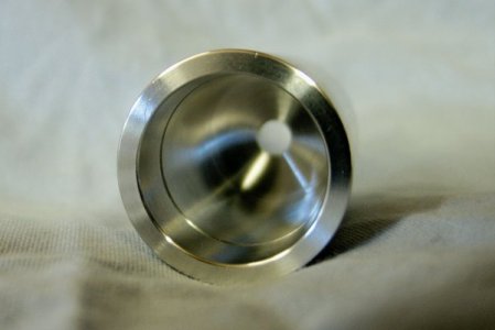
A brief case in point: An exchangeable tip live center for a Sherline lathe.
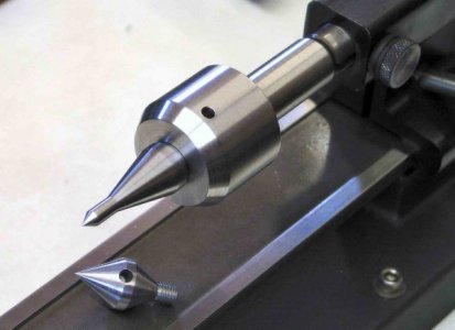
I wanted to illustrate how the information we’ve discussed was used to bore an accurate hole.
The live center above was made for my Sherline lathe and is a good example of a project we run into in a hobby shop. The OEM Sherline live center it replaced has 0.0008” TIR, which is unacceptable for close tolerance work. This one, patterned after a Royal live center, has zero TIR with the short tip and less than 0.0001” TIR with the extended tip so it works pretty well. The bearing housing and arbor are 1144 Stressproof steel and the tips are hardened and tempered O-1 steel. All work was done on a Sherline lathe.
I chose to install the Nachi double-row sealed angular contact bearing used for this project with a line-to-line press fit, which means the ID of the bearing bore must be the same dimension as the OD of the bearing so as not to impinge on internal bearing clearances once the bearing is installed. A fine finish is usually required for these fits. Recommended tolerances were +/- 3-5 microns, which I cannot even measure directly, so this was one of those projects where it took several hours just to get to the boring stage and you either hit the bore dead on or you get to start all over again.
The arbor that fit inside the bearing required the same fits so I used a sharp HSS tool to cut the arbor.
I used a 3/8” QCMI Circle Machine carbide bar with a 0.007” NR flat-topped grade CG5 insert to rough the bearing bore in the housing. The 0.007” NR insert roughs very accurately but I preferred not to risk taking fine cuts at these tolerance levels with it so I switched to a ¼” Circle Machine CCBI carbide bar with a 0.002” NR flat-topped CG5 insert to finish. I used the smaller bar because a 0.002” NR insert is not available for the 3/8” bar. From previous experience, I knew that the smaller insert usually cuts very accurately if I use a depth of cut that is two times the NR. This fully supports the nose radius and allows it to cut consistently and without chatter. While the smaller bar is more subject to deflection just based on the diameter of the bar, the bore depth was well within the extension limits of the smaller bar. I also expected that the planned finishing depth of cut would shift radial forces toward axial to further limit deflection so it was an acceptable option.
When I was a bit more than one roughing pass away from the anticipated starting point for the finishing passes I cooled the part to ambient temperature and measured it, then took my final roughing pass. I then switched to the 0.002” NR insert that allowed me to take two 0.004” deep finishing passes, measuring once more between them. The finish was excellent despite the tiny nose radius and the bore came in exactly on size.
Mikey
December 2018

