A South Bend 9 A wiring question with pictures and colors!!!!

Jonathan94596

Registered
Registered
Joined
Apr 28, 2022
Messages
8
Hi All,
I was very happy to read many of the posts here. We all love machines and many of you are wicked knowledgeable.

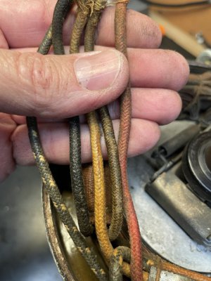
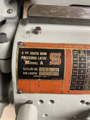
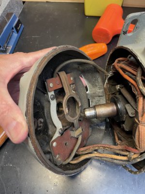
So, I’m wiring up my recently acquired 110v SB 9 precision lathe. The motor connections were a bird nest and before I got a chance to identify the mates, many connections fell apart. So, I don’t know what wires go where anymore.

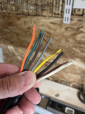
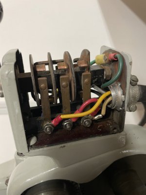
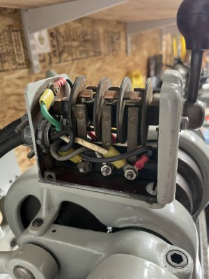
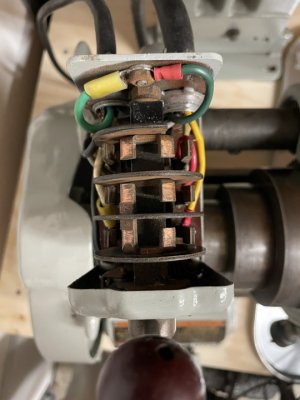
I cracked open the motor and repaired broken wires inside and extended all with new wires with IDs mapped to a picture of the original wires. The one black wire not in the image is coming off the spindle/shaft sprung contact plate which is screwed into the end cap/bearing of the motor

No label or diagram on motor.

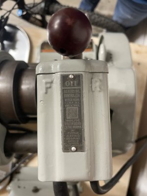
I can likely identy all the wires for the reversing switch just using a meter on the plug and bitter ends.

If anyone sees these picture and knows what the colors mean and where to connect them to the switch I’d be grateful.
 

Attachments

  • Motor Wires.JPG
    Motor Wires.JPG
    87.6 KB · Views: 19
  • 9 in South Bend Lathe.JPG
    9 in South Bend Lathe.JPG
    85.4 KB · Views: 15
  • Drum Swich Wiring.JPG
    Drum Swich Wiring.JPG
    61.2 KB · Views: 13
  • Drum Switch.JPG
    Drum Switch.JPG
    53 KB · Views: 14
  • Inside the Motor.JPG
    Inside the Motor.JPG
    89.8 KB · Views: 15
Only 5 wires coming out of the motor not 6?
Also, is this a capacitor start motor (bulge on the side of case?)
Pop the cover off the drum switch and show a pic inside
-Mark
 
There are 6. 5 from inside around windings and a 6th attached to the end cover with bearing. It’s a contact that sits on a doughnut contact on the shaft. What I’m describing is sort of visible in one of the pictures in the original post above.
 

Attachments

  • IMG_1043.JPG
    IMG_1043.JPG
    52.8 KB · Views: 9
  • IMG_1044.JPG
    IMG_1044.JPG
    72.3 KB · Views: 8
I put a meter on the motor wires. There are three pairs that have impedance. Two pairs are more or less the same and in either direction. The third pair is the 6th wire from the doughnut contact and the capacitor. That pair read very differently when measured one way or the other.
 
OK good. The funny pair is your start leg. Label those. I'll put together a diagram for you.
Can you do a shot of the switch directly overhead, not from the side? Thanks
The two other pairs are the run windings- we will need to phase them; I'll tell you how
-M
 
Last edited:
Phasing the motor requires connecting the start pair with the run windings one at a time and applying power.
You want the motor to spin the same direction for each of the two tests. Label the wires clearly afterwards.
You will need a cord with a plug. Twist wires together to make the tests, tape the ends to prevent shorts.
Use care
-M
phasing1.jpeg
 
OK good. The funny pair is your start leg. Label those. I'll put together a diagram for you.
Can you do a shot of the switch directly overhead, not from the side? Thanks
The two other pairs are the run windings- we will need to phase them; I'll tell you how
 

Attachments

  • Drum switch inside.JPG
    Drum switch inside.JPG
    60.4 KB · Views: 7
Phasing the motor requires connecting the start pair with the run windings one at a time and applying power.
You want the motor to spin the same direction for each of the two tests. Label the wires clearly afterwards.
You will need a cord with a plug. Twist wires together to make the tests, tape the ends to prevent shorts.
Use care
-M
View attachment 405571
I’ll do this later today. Your help is greatly appreciated.
 
Jonathan take a look at this diagram: does your switch look more like the "hockey stick" type or the "chopstick"/ 3-phase style?
To me it looks like the latter
Once you get the motor phased and we verify the switch type I can draw up a diagram to hook everything up--M
Drumstyles1.jpeg
 
Last edited:
I’ll do this later today. Your help is greatly appreciated.
I phase checked the motor and know the positive leads for each pair to spin counter clockwise. I tried the starter with positive at each of the pair and when it spun up if sounded like a engine that couldn’t start. It was like the starter was not disengaging because the speed was not high enough to through the centripetal switch so it clicked on and off rapidly. Would it spin if I had the winding pairs mismatched? I found continuity between the leads for each pair. It did spin up past the starter speed and ran smoothly once but other times just spun with clicking.
 
Back
Top