- Joined
- Apr 7, 2018
- Messages
- 131
This is an effort to document my build the Ageless 9 cylinder radial engine.
Some background: I have been active in hobby machining for 4 years, since retiring as a software engineer. Prior, I had no machining experience. Since embarking on this hobby, I have had many successful projects, a couple of not so successful ones, but all were educational and fun. One success is a hit-miss engine. One not quite success is a clock (runs fine for only 30 minutes). Anyway, my point here is that I am not a journeyman machinist, but I am working and learning to be a competent machinist.
I have the a PM1030V lathe with DRO and a PM727V bench mill also with DRO, a 6" rotary table. It is a small shop that is shared with wood working stuff.
Now, why did I pick the Ageless 9 cylinder radial engine for my next project?
1. It looks like a challenge. It has complicated components that will take some effort and new skills. It has a number of components are duplicated. This will require thinking in terms of production processing as opposed to one off stuff.
2. The documentation is great. It is a huge binder of over 200 pages. The drawings appear to be complete. There is an operations list for each component. This is important because I have found one difficult part of machining is to determine the order to do things.
3. The documentation contains drawings for jigs and other tooling needed. I don't have to guess.
4. It will keep me busy for a couple of years while locked down again cause the COVID pandemic isn't over.
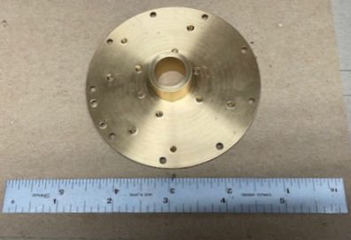
It is my intent to only upload pictures of finished components with comments on issues/non-issues found during the machining.
5. I also hope I can get answers to "how do I do this?" from you folks.
Note: I started this effort back in May 2021.
Some background: I have been active in hobby machining for 4 years, since retiring as a software engineer. Prior, I had no machining experience. Since embarking on this hobby, I have had many successful projects, a couple of not so successful ones, but all were educational and fun. One success is a hit-miss engine. One not quite success is a clock (runs fine for only 30 minutes). Anyway, my point here is that I am not a journeyman machinist, but I am working and learning to be a competent machinist.
I have the a PM1030V lathe with DRO and a PM727V bench mill also with DRO, a 6" rotary table. It is a small shop that is shared with wood working stuff.
Now, why did I pick the Ageless 9 cylinder radial engine for my next project?
1. It looks like a challenge. It has complicated components that will take some effort and new skills. It has a number of components are duplicated. This will require thinking in terms of production processing as opposed to one off stuff.
2. The documentation is great. It is a huge binder of over 200 pages. The drawings appear to be complete. There is an operations list for each component. This is important because I have found one difficult part of machining is to determine the order to do things.
3. The documentation contains drawings for jigs and other tooling needed. I don't have to guess.
4. It will keep me busy for a couple of years while locked down again cause the COVID pandemic isn't over.
It is my intent to only upload pictures of finished components with comments on issues/non-issues found during the machining.
5. I also hope I can get answers to "how do I do this?" from you folks.
Note: I started this effort back in May 2021.