- Joined
- Apr 7, 2018
- Messages
- 131
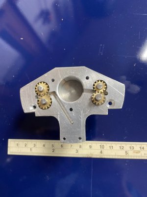
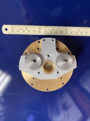
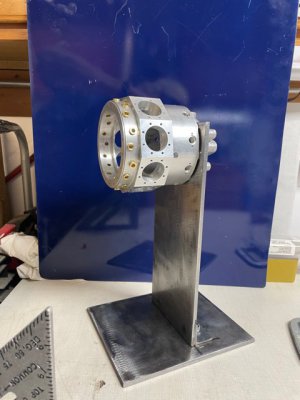
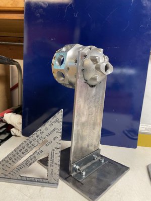
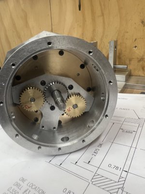
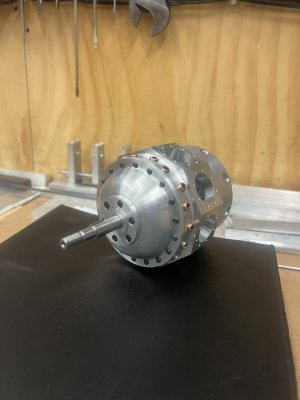
I decided to purchase the gear cutters needed for the oil pump gears rather than purchase the gears themselves. It was pretty much a wash in terms of cost and I would have three gear cutters when done. Did I mention I am somewhat of a tool junky? Anyway, the gears have been cut and are ready. Next was the stand. It is functional, not pretty. I was going to weld the stand, but realized I had better gain more experience welding before relying on the quality of my weld to handle the anticipated vibrations of an unbalanced engine. The future will be to design and build a test crankshaft that will allow me to test the oil pump efficiency. That operation will require fittings and tubing to the oil pump.
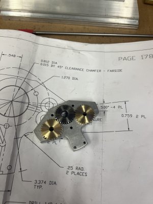
A side note. Center cutting endmills are not flat on the bottom. That's why counterbores a needed. Lesson learned.
A side note. Center cutting endmills are not flat on the bottom. That's why counterbores a needed. Lesson learned.