-
Welcome back Guest! Did you know you can mentor other members here at H-M? If not, please check out our Relaunch of Hobby Machinist Mentoring Program!
You are using an out of date browser. It may not display this or other websites correctly.
You should upgrade or use an alternative browser.
You should upgrade or use an alternative browser.
Ageless 9 cylinder radial engine build thread
- Thread starter starr256
- Start date
- Joined
- Apr 7, 2018
- Messages
- 131
No, I have not abandoned the project. I went back to work on the oil pump. It just was not putting out the flow and pressure I felt it should. I had made some decisions early on that made this component a challenge for for me. First, I decided that I would make the pump gears. I had been making gears for other engines and clocks, so felt that should be within my skill set. Second, the gears are pricey, between $25 and $30 per gear and you need 7 of them. The issue if that 4 of these gears are pump gears, not drive or timing gears. With drive gears, you can be a bit sloppy, a small bit. With a gear pump, you don't get that luxury. The distance between shafts must be accurate, the concentrically of the shafts and the well containing the gears must be precise, the diameter of the wells cannot be more that 0.001 greater than the diameter of the gears. The gap between the the gears and the bottom of the well cannot be more than 0.001. And the depth of cut of the gears must be a little greater than that specified in the Machinist's Handbook. Add to all this is that I bought cheap Brown and Sharp type gear cutters that were poorly ground such that they cut as if a button cutter. Next time I will pay the extra $50 for a good cutter.
In the end, six sets of pump gears, two housings and a lot of research later, I got it to work as I think it should. I won't be posting pictures as the parts look the same.
I did find this great 130 page document analyzing gear pump design. The guy has thought of it all. Just be up to snuff with you partial differential equations. It's "Fundamental of External Gear Pump Design" by Logan Williams.
Fundamentals of External Gear Pump Design
This report seeks to provide a foundational level of understanding of the primary mechanisms of operation and loss sources that provides designers a starting point for a gear pump design. The scope of this report includes the quantitative and qualitative parameters and metrics to define pump...
apps.dtic.mil
- Joined
- Oct 7, 2020
- Messages
- 2,115
It sure is pretty!
- Joined
- Apr 7, 2018
- Messages
- 131
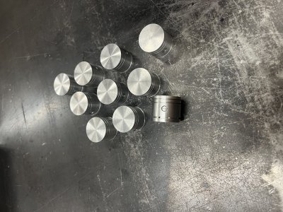
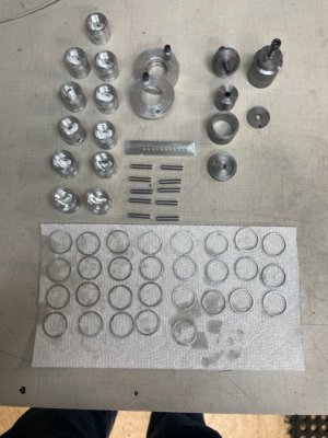
I am still at it, all be it at a slower pace. Finished the pistons, rings and pins. The pistons were a relatively simple machining task. The 0.020 oil holes were a delicate operation, but straight forward. The rings, however, were another matter. The operations and jigs were spot on, but dealing with cast iron at the called for thicknesses was touchy. They are brittle and break easily. Focus, focus, focus when handling them. Again, the 0.020 holes in the oil rings took three drill bits. Two drill bits broke quickly, before I cranked the drill RPM up 2500. Then got 100 holes with one drill bit. Lesson learned. The manual indicates that the piston, rings and pins should take 33.5 hours by a competent machinist. I took at least three times that.... Oh well.
Next effort will be on the cylinders.
I would like to design a way to test the rings when installed in the pistons in the a test cylinder. Same for the cylinder head and valves. I would like to do this testing long before general assembly. Just not sure how yet. Suggestions?
Next effort will be on the cylinders.
I would like to design a way to test the rings when installed in the pistons in the a test cylinder. Same for the cylinder head and valves. I would like to do this testing long before general assembly. Just not sure how yet. Suggestions?
Attachments
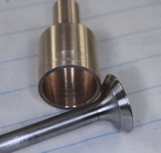
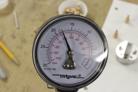
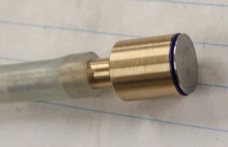
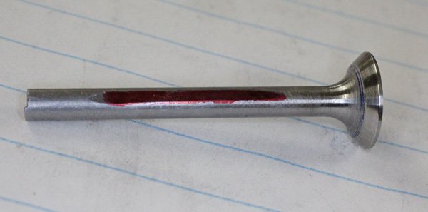
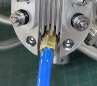
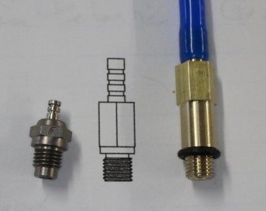
Your engine has a different parts assembly layout but maybe this will help with ideas. On my 5-cylinder radial I verified valve seal during assembly with an automotive handheld vacuum gage. The silicon hose was connected to the valve cage end. I used the same 'tester valve' on all cages. It has a flat ground on one side to allow air passage, because if you use a regular valve the annular gap is small, it will restrict flow making you think you have good seal when it may be less so. So do this dry, not with any oil on seat or stem for the same reason (although in running conditions oil fil m will assist). Pull a vacuum to the same number, say 20-25. It should hold ideally forever but drawdown decay over 30 secs is supposedly acceptable. If it goes FFfft to zero relatively rapidly, you know you have an issue to remedy. I did this before & after the cages were installed. But I believe he Hodgson has pressed in seats?I would like to design a way to test the rings when installed in the pistons in the a test cylinder. Same for the cylinder head and valves. I would like to do this testing long before general assembly. Just not sure how yet. Suggestions?
Attachments
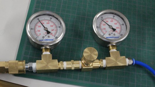
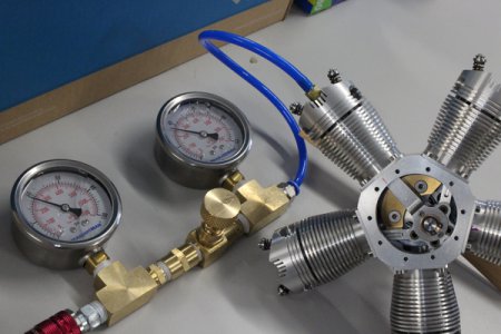
Upon final assembly I built a leak down tester from Amazon parts which basically tests everything collectively on the compression side (valves & rings). In between the 2 gages is a small orifice restrictor. On FS engine testers its a defined diameter but on our smaller scale model engines it should be proportionately smaller which is tiny. I made one by drilling a brass fitting drilled with I want to say 0.5mm but don't quote me, I'd have to check. But I also happen to have this fine adjustment needle valve which seems to work the same if you just barely crack it open. The parts just thread together so its easier. I machined a dummy plug to fit the head thread. Anyway hook up to a compressor regulator set at some number, say 40 psi & that's what the first gage will read. With the orifice/valve cracked the second gage seeing cylinder should ideally read the same & not decay. Some minor blowby is acceptable through the ring gap. Typically test at TDC but very important to lock the crank or you will get an unexpected power stroke, ask me how I know haha. I left my rear crankcase open so I could listen to any hiss or see bubbles. Idealy there should be very little to see, Hope this helps, your engine looks great!I would like to design a way to test the rings when installed in the pistons in the a test cylinder. Same for the cylinder head and valves. I would like to do this testing long before general assembly. Just not sure how yet. Suggestions?
Attachments
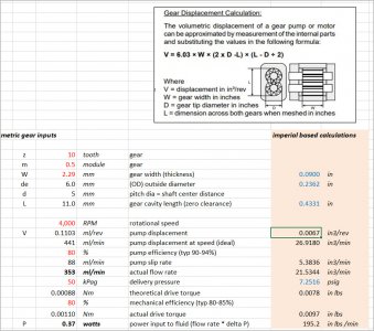
I'd really like to know more about your oil pump because that is in my future on next engine. Did you cut regular involute gears? This topic came up on model engineering forum. I plagiarized a spreadsheet from another builder so I could evaluate metric/module gears vs imperial because I can get them easier in the smaller sizes. We are still sorting out why the spreadsheet seems to indicate high flow volumes, so more to come on that front. But he took a video of his little pump & it is certainly squirting a lot of oil for such thin gears. I did read that technical paper you referenced.... along with about 5 others. Unfortunately its like a jigsaw puzzle, they specify some parameters but not others. There are Hodgson builds on other forums, I'm sure the pump was discussed. I can find links if you haven't already seen some builds. Here is where I'm at right now with my spreadsheet. the governing equation is actually very simple but like I say, something seems amiss so we need to get back on this.