Another Treadmill Motor Speed Controller conversion thread

There had been some discussion about the suitability of this controller.
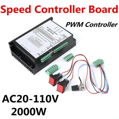
The primary stumbling block was the absolute maximum input voltage of 110 volts, making it unsuitable for use in the US. At the end of last month I ordered one of these through Amazon ( I elected to pay the premium price because of Amazon's return policy and because the estimated shipping time was faster). Yesterday, it arrived and I have put it through some preliminary tests.

The controller is essentially plug and play. There are four connections to be made, all through a provided connector; AC in and motor out. A prewired plug for on/off, fwd/rev, and speed is provided. Line voltage here can go as high as 127 volts at times so I powered it through a Variac. At 90 volts in, my motor speed was 3160 rpm (calculated from measured spindle speed and pulley ratios) and at 105 volts in, the motor speed was 3570 rpm.

For a permanent setup, I wound a bucking transformer which allows me to select output voltages in 5 volt increments from 90 volts to 150 volts. I will elect to go with a 105 volt output to provide some margin of safety for the input voltage.

Another concern that I had was possible interference with my electronic lead screw and/or my TouchDRO. So far, there has been no indication of any interference. When the modification is complete, I will post the details in a separate thread but for now this information will hopefully prove useful to others considering replacing their OEM motor with a D.C. brush motor.
 
So far, my cost for the PWM is zero,, due to parts on hand. The electrolytic capacitors come from computer power supplies. If I were buying all parts new, the most expensive parts are the MOSFET power transistor, the bridge rectifier, the potentiometers, and the high voltage electrolytic capacitors .

From DigiKey, a 15 amp power transistor can be had for less than $1 and 25 amp bridge rectifier for less than $2. The combined total of the remaining i.c.'s for less than $2, a handful of resistors and a half dozen capacitors for around $1. The power supply for the control circuitry would be one of the ubiquitous wall warts.

Jameco has a variety of potentiometers for under $2. The electrolytic capacitors are fairly expensive bought new but every computer power supply has several, as do all switching power supplies. Banggood has 5 pcs. 680mfd 300v elctrolytics for $12.65. Miscellaneous components are a p.c. board, enclosure, heat sink, and wiring. I haven't done a a full BOM as some parts may change depending on what I have on hand and test results.

Do you mind sharing your schematic I believe i have all the components lying around to build this.


Sent from my iPhone using Tapatalk
 
Do you mind sharing your schematic I believe i have all the components lying around to build this.


Sent from my iPhone using Tapatalk
I gave up on the DIY version of a controller. The reasons were several. For some unexplained reason, the MOSFET transistors all died an instant death. The simple circuit in post #63 that I bought was not able to output a proper waveform. I suspect that it was because the output from the circuit was from a MOSFET. Trying to access the driving circuit on that tiny board was an excercise in futility. I could have laid a new board out based on the circuit that I traced but it had one other flaw in that it didn't incorporate a slow start feature.

The other circuit that I pulled off the internet did have a slow start feature but I never could get it to work.
I suspect that it was due to my trying to run the cycle frequency at 20 kHz rather than a relativley lower frequency that the author had designed. The issue came with the trigger signal for the PWM second stage. The pulse has to be shorter than the shortest desired pulse and R1, R2 and C1 limit the width of that pulse. The 555 has limitations for the allowable valuers for those components. I could have used a differentiator between IC1, pin 3 and IC2 pin 2 to correct that. However, there were other issues with the back end of his circuit. Frankly, it was rather wonky.

Finally, I was faced with buying another batch of MOSFETs and Schottky diodes and the cost would have set me back about $25 (I was buying extras). I realized that buying the controller in post #71 was probably a better path. Had I been willing to wait, I could have bought it for around $50.

My testing of the controller has acceptable so far. Unlike the warnings in the directions (the ones on Aliexpress are better), it does seem to have some protection built in for sudden motor reversal. The motor power is killed for a few seconds before it powers up for reverse. It also appears to have a soft start feature. The only problem that I ran into is in trying to use the OEM reversing switch on my 602. The controller requires an open switch to start which is not an option on most reversing switches. It is possible that the sense of the input can be reversed but without a schematic of the circuit, I am loathe to try. I decided to just use another switch. I made an adapter plate to accept my new switch and am ready to put it all back together.

The circuit does require running on a reduced voltage and I needed a stepdown transformer to accomplish that. I used an old core from a Variac to wind a a stepdown transformer. I bought copper transformer wire for the project at a cost of $15 for doible the wire that I needed. I will be posting a thread on that build.

I stll think that it is possible to buid a circuit on the cheap providing someone has done the up front work to develop a proven circuit.
 
I'm with @Janderso , I'm lost. Almost understand what's going on but not quite.

I've got (4) salvaged sets in milk crates in the attic, and I've got to get the Logan converted, it's past being on it's last leg.
 
I gave up on the DIY version of a controller. The reasons were several. For some unexplained reason, the MOSFET transistors all died an instant death. The simple circuit in post #63 that I bought was not able to output a proper waveform. I suspect that it was because the output from the circuit was from a MOSFET. Trying to access the driving circuit on that tiny board was an excercise in futility. I could have laid a new board out based on the circuit that I traced but it had one other flaw in that it didn't incorporate a slow start feature.
...

Hi RJ. The problem with using the circuit in post 63 is that it is not meant to drive a MOSFET gate. For example, with Q1 off, M- will go high through the 1K resistor and LED. A large MOSFET requires a lower drive. Furthermore, one would really want to see the drive go low with Q1 is off. A simple modification would be to run the gate of Q1 to a NPN totem pole driver with say 22 ohm gate resistors for the larger transistors. This would be snappier, and would have the correct polarity. Of course, some sort of snubber would be required, and you will also need an isolated oscilloscope to debug this circuit. There are good differential probes available.
 
Hi RJ. The problem with using the circuit in post 63 is that it is not meant to drive a MOSFET gate. For example, with Q1 off, M- will go high through the 1K resistor and LED. A large MOSFET requires a lower drive. Furthermore, one would really want to see the drive go low with Q1 is off. A simple modification would be to run the gate of Q1 to a NPN totem pole driver with say 22 ohm gate resistors for the larger transistors. This would be snappier, and would have the correct polarity. Of course, some sort of snubber would be required, and you will also need an isolated oscilloscope to debug this circuit. There are good differential probes available.
Yes, I had figured that out. Ideally, I would remove Q1, D7, R7 and D1 from the circuit completely and add the necessary driver and high power MOSFET circuitry. The problem was that with SMD parts on a tiny circuit board, it becomes tricky. It's a shame because it would have been a great shortcut for someone that didn't want to get into the nitty gritty of building a circuit. If I had continued, I would have started from scratch with through hole parts. There is at most only a dollar or two in parts left. It still didn't provide me with soft start though.

I do have a scope and isolation transformer and I may take up the project again at some time although I no longer have a need for it.
 
Update on the 602 D.C.motor conversion.

The modification to the lathe is complete. All that remains is to replace the Variac with the bucking transformer. The controller is too large to fit inside the 602 electrical enclosure so I mounted it on the back cover of the electrical enclosure using a piece of 2 x 2 x 1/8" aluminum angle. It is possible that some stray chips could fall inside through the ventilation slots and I will put a shield to prevent that occurrence. So far, no noticeable interference with the ELS or DRO. I replaced the OEM FWD/REV switch with a 2 pole 3 way rotary switch which necessitated making an adapter plate. For the speed control pot, I enlarged a previously made hole above the FWD/REV switch to accept the 3/8" pot bushing. I used a 10K wirewound pot for the control. The effective control trange is limited to the central portion of the pot. Ihad assumed that the pot was a linear wind but it is possible that it isn't a simple check with an ohmmeter will tell.

I am operation on 105 volts applied to the controller with 122 volts line voltage which should give me a safe margin to allow for fluctuating line voltage. Ihe 602 contactor will actuate on as low as 90 volts so I'm OK with operating on reduced voltage. I am seeing a maximum speed of 3900 rpm as opposed to the rated no load speed of 4090. Current draw at maximum speed, no load is 3 amps.

I have noticed one quirk with the controller. On startup, it will slowly build up speed over the course of about 7 - 10 seconds. The phenomenon is enhanced at lower speeds (20% of f.s.)where it can take up to thirty seconds I haven't put an oscilloscope on the controller to see what is happening but I suspect that the slow start feature is the cause. More than likely, a capacitor is used to delay the control voltage reaching its final value. It's not something that is a deal breaker but it is somewhat an annoyance. It is also possible to control controller externally with a PLC or through something like a Mach 3 control.

The last bit of work is to make a mount for the bucking transformer. I will install it below the lathe table where it will be protected from any swarf and out of the way.
 
Good thread here.
I would just like to mention that I put together the exact dc controller that was linked to in post #1, from Mike Man Made.
I don't know about it being noisy or too dirty for sensitive equipment, but it was cheap and easy. When you but a pot you have to get a kit and try different ones to dial in your speeds and range of power.
I used it for over a year and had no problems, well one, my 100 year old lathe was way overpowered.
 
Must include pictures or it never happened :)
I thought of doing some pictures but there is nothing really impressive to be seen. I do have pictures of the bucking transformer build and will include them with the thread on the build.

Here is a photo of the modified 602 controls and of the back side of the lathe showing the controller. The ELS display is in the upper right of the first photo and the light gray enclosure next to the black PWM controller houses the circuitry for the ELS.
PWM Controller  1.JPG PWM Controller 3.JPG
 
Back
Top