- Joined
- Mar 21, 2020
- Messages
- 81
PWM and Motor work
Hello all hope you all had great holidays!!!
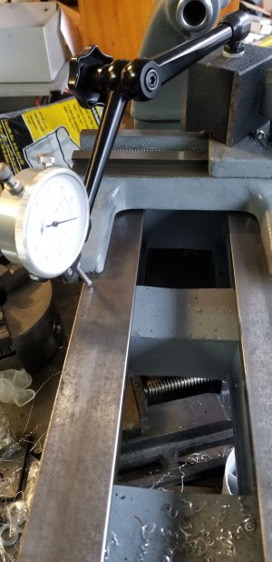
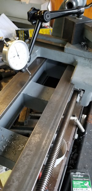
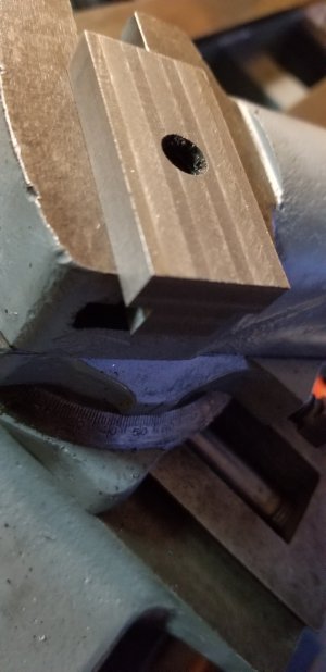
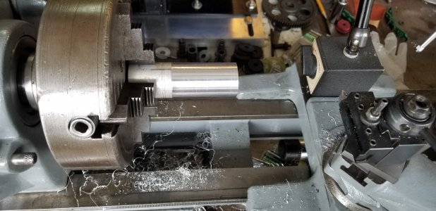
Well I have been working on the new travers gearbox that I mentioned previously in this thread and its been given me problems so I decided to take a break from that installation and move to something else. The lathe resurrection is basically completely done except for getting that travers case working and general tweaking of the lathe. We will post more on the above later.
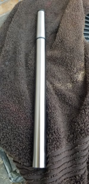
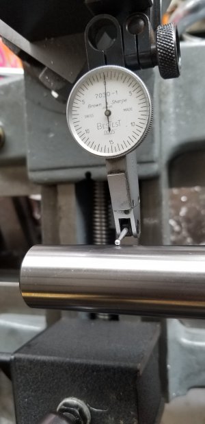
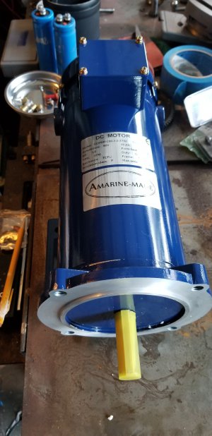
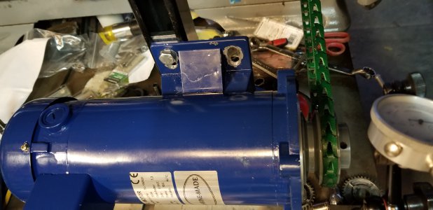
Motor: below is the photo of the motor I went with. It appears nice and is readily available. It's a 90VDC motor 1HP 10amp and is rated for continuous duty. The build quality also looks pretty good. Unfortunately its blue and doesn't match the paint scheme lol lol.
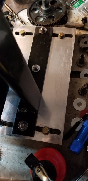
Motor pulley: I purchased a 3" dual V belt cast iron pulley to accommodate two of the pulley locations in the head stock. The pulley has two sets crews and runs true. Like the motor looks good however time will tell.
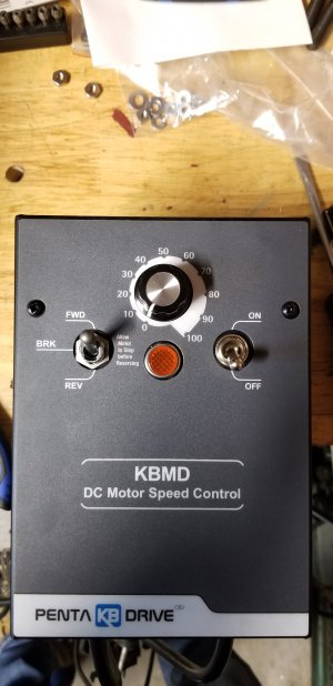
PWM: I went with the KBMD Penta PWM and the below information is my thoughts on this device...
The KBMD is well made and worth the extra money compared to others regarding its build quality however it's not perfect... let's look
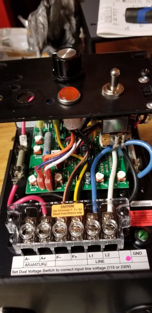
1) If you're looking at buying one you will also need to purchase the extra parts for it to work. If your running a 1HP 90VDC motor like me you will need the below parts and the total price is $236 shipped. You will need the armature fuse rated for a 1HP motor and the plug in resistor rated for a 1HP motor. If your running a 1HP motor or 2HP motor you will also need the optional heat sink. Running less than a 1HP motor the heat sink isn't required. Now if you want the forward/reverse and brake switch you will also need that option. Check the website for the required options for your size motor. Parts REQUIRED for any size motor are the armature fuse and the motor plug in resistor.
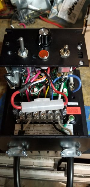
2) comes in a nise case and the switches operate nicely.
3) Has all the required trimming pots on the board to adjust to your motor spindle speed.
4) Directions are pretty good. During the installation of the forward/reverse switch I was a bit confused for the directions make reference to short and long red and black wires however with the switch not installed the are basically the same length however when you install the switch it will become clear the difference between the short and long pairs. My long pair of red and black wires had a wire tie and the other pair didn't.
5) Installation of the forward/reverse switch will require some modifications in my mind!!. First the switch comes with a nut attached and the manual said a spare nut is provided incase you lose the original nut. USE the spare nut its smaller then the one original on the switch and fits inside the cover mounting holes were the original is to big and you will not be able to install the case cover!! The case cover is installed with two screws on the top as the manual points out. The cover is hard to slide off I actually went looking for other screws thinking it was still screwed in someplace lol.
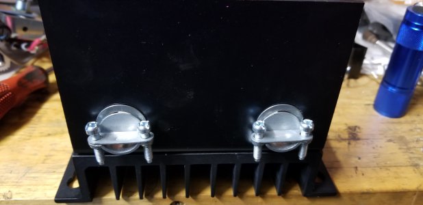
6) Forward/reverse switch placement and mod. Ok now looking at the photos below you will see that the installation of the switch placed the switches backing plate almost touching the armature fuse!!! I removed the original fuse and installed a traditional plastic fuse holder. I didn't use the original fuse holder because I didn't want to drill into the case however one has room to do that if one chooses.
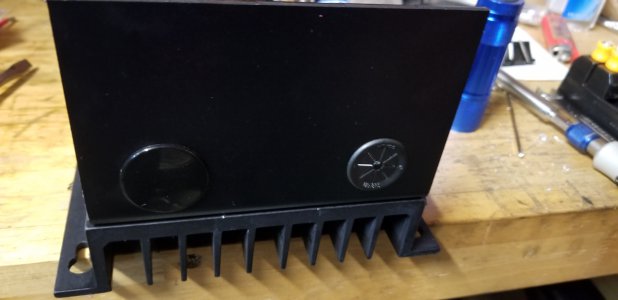
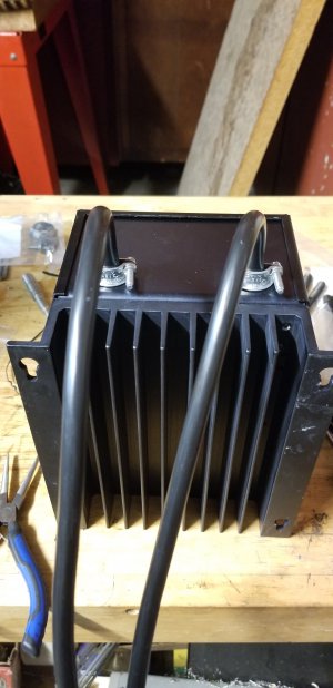
7) The case: looking at the photos you will see the new 3/8 electrical strain reliefs I installed. Strangely the case had one grommet installed and the other hole was just a cover. The hole with just the cover is larger then the other hole however the 3/8 size fits both.
8) Case and switch: when the switch is installed into the case it covers one of the access holes to the trimmer potentiometer!! I was able to still access it using the adjacent hole for the other trimmer ( just barely) one may opt to make your motor speed adjustments before installing the forward/reverse switch.
9) Motor brake: The motor brake works well however given that we have zamic parts in this lathe I don't think I will utilize this option.
10) Power: This PWM supports 110VAC and 220VAC power input from your mains. One doesn't need to have a separate DC power supply like other PWM. My unit was shipped to me in the 220VAC position so living in the US I moved it to 110VAC.
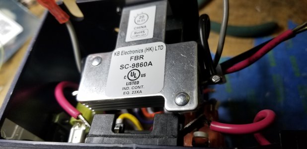
11) Heatsinks: in the photos below you will see the optional heat sink attached to the bottom of the case. This option is required according to the manufacturer for any motor from 1HP up. I'm actually not sure how effective this is for this unit has 6 transistors mounted to the back of the case. In order to deliver maximum heat transfer the sinks should be attached to the back of the transistors and not on the bottom of the case. I might make a aluminum sink for this later to mount behind the transistors.
Now I'm working on the actual motor mounting system and will post that when completed.
Hello all hope you all had great holidays!!!
Well I have been working on the new travers gearbox that I mentioned previously in this thread and its been given me problems so I decided to take a break from that installation and move to something else. The lathe resurrection is basically completely done except for getting that travers case working and general tweaking of the lathe. We will post more on the above later.
Motor: below is the photo of the motor I went with. It appears nice and is readily available. It's a 90VDC motor 1HP 10amp and is rated for continuous duty. The build quality also looks pretty good. Unfortunately its blue and doesn't match the paint scheme lol lol.
Motor pulley: I purchased a 3" dual V belt cast iron pulley to accommodate two of the pulley locations in the head stock. The pulley has two sets crews and runs true. Like the motor looks good however time will tell.
PWM: I went with the KBMD Penta PWM and the below information is my thoughts on this device...
The KBMD is well made and worth the extra money compared to others regarding its build quality however it's not perfect... let's look
1) If you're looking at buying one you will also need to purchase the extra parts for it to work. If your running a 1HP 90VDC motor like me you will need the below parts and the total price is $236 shipped. You will need the armature fuse rated for a 1HP motor and the plug in resistor rated for a 1HP motor. If your running a 1HP motor or 2HP motor you will also need the optional heat sink. Running less than a 1HP motor the heat sink isn't required. Now if you want the forward/reverse and brake switch you will also need that option. Check the website for the required options for your size motor. Parts REQUIRED for any size motor are the armature fuse and the motor plug in resistor.
2) comes in a nise case and the switches operate nicely.
3) Has all the required trimming pots on the board to adjust to your motor spindle speed.
4) Directions are pretty good. During the installation of the forward/reverse switch I was a bit confused for the directions make reference to short and long red and black wires however with the switch not installed the are basically the same length however when you install the switch it will become clear the difference between the short and long pairs. My long pair of red and black wires had a wire tie and the other pair didn't.
5) Installation of the forward/reverse switch will require some modifications in my mind!!. First the switch comes with a nut attached and the manual said a spare nut is provided incase you lose the original nut. USE the spare nut its smaller then the one original on the switch and fits inside the cover mounting holes were the original is to big and you will not be able to install the case cover!! The case cover is installed with two screws on the top as the manual points out. The cover is hard to slide off I actually went looking for other screws thinking it was still screwed in someplace lol.
6) Forward/reverse switch placement and mod. Ok now looking at the photos below you will see that the installation of the switch placed the switches backing plate almost touching the armature fuse!!! I removed the original fuse and installed a traditional plastic fuse holder. I didn't use the original fuse holder because I didn't want to drill into the case however one has room to do that if one chooses.
7) The case: looking at the photos you will see the new 3/8 electrical strain reliefs I installed. Strangely the case had one grommet installed and the other hole was just a cover. The hole with just the cover is larger then the other hole however the 3/8 size fits both.
8) Case and switch: when the switch is installed into the case it covers one of the access holes to the trimmer potentiometer!! I was able to still access it using the adjacent hole for the other trimmer ( just barely) one may opt to make your motor speed adjustments before installing the forward/reverse switch.
9) Motor brake: The motor brake works well however given that we have zamic parts in this lathe I don't think I will utilize this option.
10) Power: This PWM supports 110VAC and 220VAC power input from your mains. One doesn't need to have a separate DC power supply like other PWM. My unit was shipped to me in the 220VAC position so living in the US I moved it to 110VAC.
11) Heatsinks: in the photos below you will see the optional heat sink attached to the bottom of the case. This option is required according to the manufacturer for any motor from 1HP up. I'm actually not sure how effective this is for this unit has 6 transistors mounted to the back of the case. In order to deliver maximum heat transfer the sinks should be attached to the back of the transistors and not on the bottom of the case. I might make a aluminum sink for this later to mount behind the transistors.
Now I'm working on the actual motor mounting system and will post that when completed.
Attachments
-
 20210116_195638.jpg972.4 KB · Views: 17
 -
 20210104_171936.jpg956.3 KB · Views: 12
 -
 20210116_084211.jpg978.7 KB · Views: 8
 -
 20210116_194736.jpg953.4 KB · Views: 8
 -
 20210116_101614.jpg1.7 MB · Views: 9
 -
 20210116_084249.jpg1.8 MB · Views: 7
 -
 20210116_084740.jpg1.9 MB · Views: 5
 -
 20210116_195827.jpg903.1 KB · Views: 13
")