Back at the well thirsty for knowledge

Maybe a bit unclear as to the setup you have. As mentioned the motor should be directly wired to the VFD, switching the VFD motor output while it is running can result in damage and negates the feedback in sensorless vector mode. If you are then repurposing the current motor switch to activate the VFD contacts, they are are at 24VDC and a few mA. They need contacts that are designed to work with this low voltage/current. In the past both myself and others have tried to use switch gear and contactors that had been previously used to switch the motor 230VAC and had developed resistance across the contacts. As a result when subsequently used for switching the VFD inputs they often made poor intermittent connections. That is the reason for replacing the current motor rotary switch with a new 3 position maintained switch.
 
Maybe a bit unclear as to the setup you have. As mentioned the motor should be directly wired to the VFD, switching the VFD motor output while it is running can result in damage and negates the feedback in sensorless vector mode. If you are then repurposing the current motor switch to activate the VFD contacts, they are are at 24VDC and a few mA. They need contacts that are designed to work with this low voltage/current. In the past both myself and others have tried to use switch gear and contactors that had been previously used to switch the motor 230VAC and had developed resistance across the contacts. As a result when subsequently used for switching the VFD inputs they often made poor intermittent connections. That is the reason for replacing the current motor rotary switch with a new 3 position maintained switch.
Okay thanks now I understand. if I measured the resistance of FWD and REV on the switch how many ohms would be acceptable?
 
I do not have a figure for the ohms for resistance, and it can vary at times based how the contact closes. Low voltage switch gear usually has contacts that are silver alloy, or gold coated to assure high conductivity. Contact resistance is below 0.25 ohm, acceptance level I have seen is less than 25 milliohms for micro/mini switch gear , so not measurable with a standard ohm meter. Small signal test currents are on the order of 5-10V at 5 mA. Switch gear to handle motors are a completely different, and are designed to handle very high current starts. Contact resistance also changes over the life of a switch due to multiple factors, the higher the voltage/current the higher the failure rate, and also depends on the type of load, voltage level and if AC or DC as to switch gear life for the application. Switch gear often include rated mechanical life and load life at maximum ratings. My direct experience with using high voltage switch gear for low voltage VFD signals is that they are iffy when new and worse when used. It may work, but it may also be intermittent or not work well.

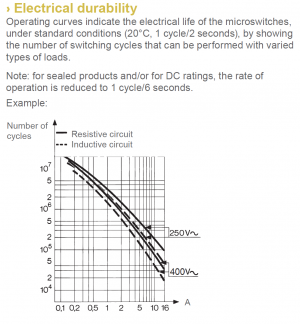
Just an example of the issues with small switches, and larger switch gear is worse when it comes to small signal levels that they were never designed for.


1680284378740.png
 
I do not have a figure for the ohms for resistance, and it can vary at times based how the contact closes. Low voltage switch gear usually has contacts that are silver alloy, or gold coated to assure high conductivity. Contact resistance is below 0.25 ohm, acceptance level I have seen is less than 25 milliohms for micro/mini switch gear , so not measurable with a standard ohm meter. Small signal test currents are on the order of 5-10V at 5 mA. Switch gear to handle motors are a completely different, and are designed to handle very high current starts. Contact resistance also changes over the life of a switch due to multiple factors, the higher the voltage/current the higher the failure rate, and also depends on the type of load, voltage level and if AC or DC as to switch gear life for the application. Switch gear often include rated mechanical life and load life at maximum ratings. My direct experience with using high voltage switch gear for low voltage VFD signals is that they are iffy when new and worse when used. It may work, but it may also be intermittent or not work well.

Just an example of the issues with small switches, and larger switch gear is worse when it comes to small signal levels that they were never designed for.


View attachment 443057
Thanks
 
You should not be using the current rotary motor switch to control the motor operation when connected to the VFD, I would recommend removing it. External speed pot has 3 connection 11 is the 0V potential, 12 is the sweep voltage, 13 is the +10V high side. Input 12 sweeps from 0-10V. To set the frequency control to the external pot. F01 = 1 (frequency command 1, voltage input to terminal 12) and C30 = 1 (frequency command 2, voltage input to terminal 12). To run the motor from the VFD inputs FOR and REV signal inputs program F02 = 1, this requires the 3 way external switch. CM is common connected to either FOR or REV input to activate that command.

View attachment 442973View attachment 442990

View attachment 442995
View attachment 442996
I followed your advice and did not use the old rotary switch. I also hooked the remote pot and set f 01 to 1 and it all works perfect. Only temporary for now as soon as I get the rest of the materials, I will mount the VFD inside the enclosure and wire it all permanently. Thanks for your help and patience helping me to understand.
 
Back
Top