[How-To] Bevel corner of a cube.

I got it, I made a plane through 3 points and then an offset plane and then used the circular pattern tool to get all the rest the corners.

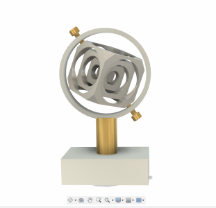
Here is what I plan on making. Thank You @RJSakowski for both the pro tip on cutting the corners and the plane through 3 points idea.
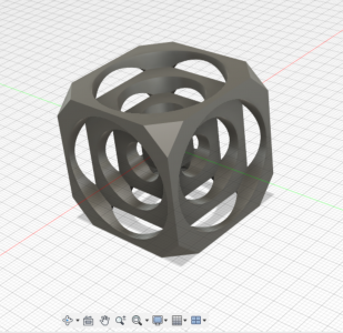
Screenshot 2023-07-22 212407.png
 
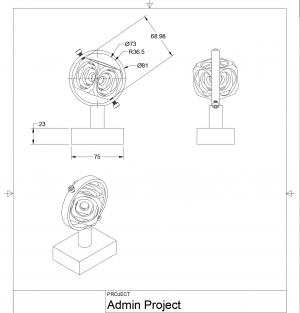
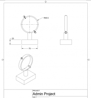
The stock for the turners cube should be here tomorrow. In the meantime, I have been working on a stand. Still talking about the drawing, on the 2D sketch drawing (I think that is what it's called) how do I draw the angle for the pivot screws? I know what they are I just don't know how to draw or display them. Here is what I have so far.


Screenshot 2023-07-27 070514.png

Screenshot 2023-07-27 065529.png


Screenshot 2023-07-27 081216.png
 
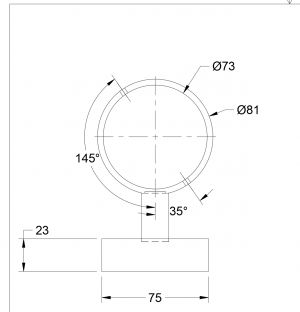
When you are in the drawing, you can choose "Angular Dimension" from the dimensions drop down. Then select two lines on the drawing and it will add a dimension for the angle between the two lines. You might have to use the BASE as the horizonal reference. There might be a way to add a temporary Vertical or Horizonal line in the drawing and then hide it after the dimension is created.

btw, instead of soc cap screws, have you thought about using 'grub" screws that come to a point and if you size it correctly the top could be flush with the surface of the ring. There are ones that come to a point and ones that have a rounded end

LINK TO MCMASTER_CARR
 
So far, I haven't been able to accomplish the task. I got close once I must still be missing something. On the 3D sketch I have a construction plane set at 145°. So, looking at it from the front side the screw on the lower right will be at 35° and the one on the upper left would be at 145°.

Anyway, on the cap screws, I am going to single point two brass pointed screws and knurl the ends. They don't need to be like that as they should never need adjusting. I just like the contrast, it kind of reminds me of an old globe. I'm going to try and single point the screws so they fit tight and won't work loose on their own.
 
Solidworks is only going to work for me as long as I can maintain a safe Win7 install. Microsoft, google, and Adobe have all pulled support, so the clock is ticking. I'm considering Fusion, not by choice obviously.

With SW, I can simply select the three vertices that form the corner, click the bevel/chamfer button, enter the parameters, and it's done without any extra geometry. Offset planes can be more powerful and are better in a lot of ways, but are considerably harder to edit if you want to tweak something. Does Fusion have an analogous operation to bevel/chamfer?
 
So far, I haven't been able to accomplish the task. I got close once I must still be missing something. On the 3D sketch I have a construction plane set at 145°. So, looking at it from the front side the screw on the lower right will be at 35° and the one on the upper left would be at 145°.

Anyway, on the cap screws, I am going to single point two brass pointed screws and knurl the ends. They don't need to be like that as they should never need adjusting. I just like the contrast, it kind of reminds me of an old globe. I'm going to try and single point the screws so they fit tight and won't work loose on their own.

The Angular Dimension is available in the 2D Drawing, Might be in a Sketch but I think any dimensioning in a sketch is to create constraints. the 2D Drawing is where you put dimensions to communication. You said you are having problems with that. Is it selecting the two lines? Accessing the dimensioning command? Something else?
 
Solidworks is only going to work for me as long as I can maintain a safe Win7 install. Microsoft, google, and Adobe have all pulled support, so the clock is ticking. I'm considering Fusion, not by choice obviously.

With SW, I can simply select the three vertices that form the corner, click the bevel/chamfer button, enter the parameters, and it's done without any extra geometry. Offset planes can be more powerful and are better in a lot of ways, but are considerably harder to edit if you want to tweak something. Does Fusion have an analogous operation to bevel/chamfer?
Pontiac, I used AutoCAD for 25 years before I had to give up. Moving to Fusion 360 has been a bigger learning curve that I expected. Many things are similar but the work-flow or probably better described as the Thought-Flow is different with Fusion360 than with AutoCAD. This makes some (many) thing easier but some things have just been big head-scratchers as I scourer You-Tube to make sense. Especially hard for me to get used to is the concept of Constraints, were design elements are made to be relative to other design elements. Seems powerful but no where close to intuitive for me (yet), As they say, practice makes perfect so I keep after it and it gets easier each design.
 
I finely figured it out. I had to sleep on it, I guess.

The first thing I had to do was make the drawing visible with hidden edges. Then I turned off the bolts and marked the center line of the bolt holes, at that point I had a line to measure to.

Thanks for the tip on using the Angular Dimension function.

I watched a YouTube on making a knurled bold last night, so I'll have to work on that.

So many things to learn and such little time!

Screenshot 2023-07-28 071644.png
 
OK here is a monkey wrench for you.

Since this is a "turners" cube, how about make the corners spherical?
Both modeling and making would be easy. For modeling just use a sketch plane thru the center of the part draw the half arc to the center-line add 3 lines for the outside area and do a cutting revolve to knock off all the corners at the same time. To make just hit it with the ball turner. No ball turner, new project time...

If you want them flat just for modeling make a sketch plane rotated 45° from the center-line draw 4 triangles and do a symmetric cutting extrude. Create a second sketch plane 90° from that one and repeat.
Another way to get the sketch planes is to use 2 opposite edges to define the plane.
Another way is to pick 3 corner points.
Another way is to create an offset plane that is the distance needed for the flat of the corner to the center of the part. and extrude outward, but you would have to do this 8 times.

With everything in CAD I always say that there are at least a half dozen way to do everything and at least 3 of them will be good ways.


For your holder, in order to have something to dimension to I have been known to put a tiny feature in the 3D model so that I have something to dimension to. I am talking TINY like a feature they might only be 0.000001. You will never see it in the model or the drawing unless you are really zooming in on the spot. At most it will be 1 pixle on screen and one dodt as small as you printer can make on a printed page. but the software knows it is there and will let you dimension to it.
 
Back
Top