Blohm Simplex Surface Grinder Q's

ARM

Active User
Registered
Joined
Dec 8, 2011
Messages
268
Hi Guys
Hope somebody is familiar with this Machine which we have just bought.
The GRINDING WHEEL FLANGE has really been butchered, if not massacred. Don't eyeball pic !!! We will need to remove the WHEEL at some point in time and rather know now exactly how to, than later. The method in the Manual we have is complicated enough and we would appreciate if somebody could simplify this in "lay terms". Also, would we be able to get a replacement, seeing this is such an old Machine ???

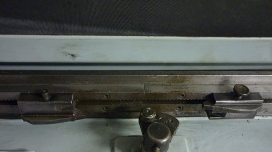
The other items are the LONGITUDINAL TABLE STOPS which don't want to move, even after loosening the small holding Bolt. We definitely require the Longer Table Travel. The Left Side Stop has its 4.0mm Bolt broken at the stem anyway and we would need remove that initially to get things going and machine a replacement. ( cc. pic attached )
Would appreciate some enlightenment here
TIA
aRM 026.JPG 020.JPG
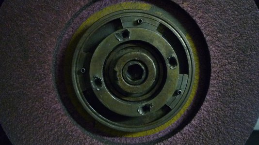
 
Somebody beat that one up pretty good.

If the wheel turns clockwise as you are facing the grinder then the hub will have left hand threads. The hex socket is the end of the spindle. The nut with the ''keyway'' secures the hub to the spindle. The flange with the 4 spanner holes secures the wheel to the hub.

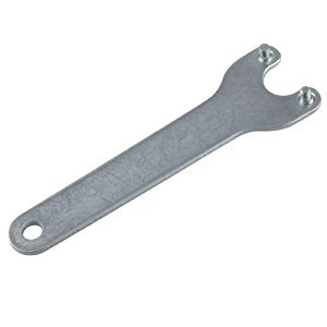
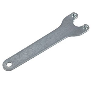
I would make a spanner to fit the flange, and maybe drill new holes for the spanner pins.

31VGImuRKvL._SY300_.jpg
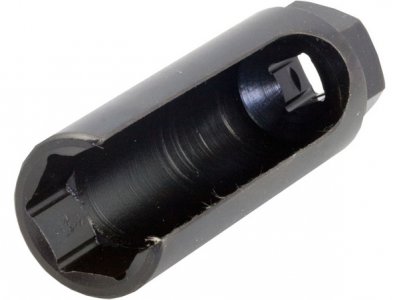
You will have to build a special wrench to remove the hub nut, or maybe mill a hex on it to use a O2 sensor socket, so you can still hold the spindle with the hex wrench.

O2Socket_LRG.jpg

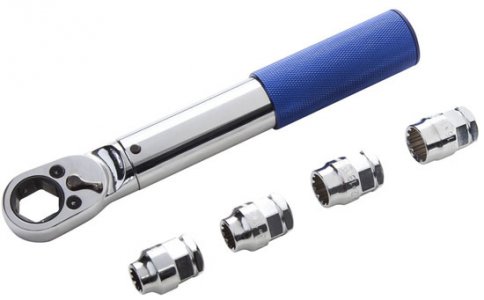
A hollow socket would also work if the hub nut was a hex rather than a keyway.

Kobalt-Xtreme-Access-Ratchet-with-Socket-Storage.jpg


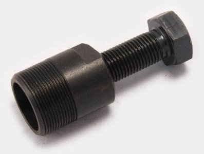
The inside of the hub is normally threaded and you use a tool like this to remove the hub from the spindle after you remove the nut.

piaggio-flywheel-puller-4499-p.jpg


I would say the travel stops are just stuck. After loosening the screws tapping them with a small hammer or a brass punch should break them free.

I can't help with sourcing new hubs.
.
.
 
Jim Dawson Esq
Hello there
Thanks a stack for this. Just checked - we do have an Allen key that fits nicely, for what they call the " Differential Screw" . So that's a start for us. Apparently there is a mark on this Diff Screw (can be seen in pic at the Eight-o'-clock position) which must coincide with the mark on the Flange, seen at the One-o'clock position. Need to physically verify that first thing in the morning, IA.

The Nut with the "Keyway" is referred to as the Threaded Bush in the Manual. However, that ugly-looking slot which U see as looking like a "Keyway" is actually part of the "Bush-Mechanics" trademark, which was not supposed to be there in the first place !!! That, we reckon will require replacing as well.

We were also thinking of getting or making a Spanner exactly like the one U have suggested. So U have confirmed what we need to do which is another must project. Only thing is we need to work out the nitty-grittys on how to tackle this with the right Dimensions.

Once again, much appreciate the feedback. Gives us some hope that all is not lost and there's some light at the end of the tunnel, LORD Willing
Take care
aRM
 
If the wheel turns clockwise as you are facing the grinder then the hub will have left hand threads. The hex socket is the end of the spindle. The nut with the ''keyway'' secures the hub to the spindle. The flange with the 4 spanner holes secures the wheel to the hub.

I would make a spanner to fit the flange, and maybe drill new holes for the spanner pins.

You will have to build a special wrench to remove the hub nut, or maybe mill a hex on it to use a O2 sensor socket, so you can still hold the spindle with the hex wrench.

31VGImuRKvL._SY300_.jpg
I would say the travel stops are just stuck. After loosening the screws tapping them with a small hammer or a brass punch should break them free.

I can't help with sourcing new hubs.
.[/QUOTE]

JIM DAWSON Esq
Hello again JIM
We tried sourcing that SPANNER which U rightly suggested we get. The machine Suppliers don't even have one, and its not that easy getting one of "e" at a reasonable Price. There are similar Auto-Tooling ones with different pin sizes and even adjustable to the 3" which we require. However, these are not cheap with shipping. So its back to the drawing board for us. We will need fabricate one to the correct Dimensions, starting with an accurate Drawing.
We are thinking of using 10mm steel for the body. Don't know if we need go heavier ???
What is worrisome is mounting the two Pins. How would U suggest we go about this ???
Recalling the auto Wrench we saw - one way we think would be to turn the Pins with Threaded Bases to Screw onto the Spanner / Wrench, whilst hoping that 10mm thickness would be ample meat to hold those threads. Maybe a little tricky for us working to those smallish dimensions !!! But it can be done.
This method may require thicker material for the spanner.
Don't really know if we are on track here ???
Do kindly let us have Your suggestions here and or critic our method which may be totally incorrect.
The Travel Stops required "squeezing" the Nut to release them, and Bobs your uncle - they moved nicely.
Presently we only need sort out the Table traverse, the Forward / Back movement which is only working on Rapid. Still battling with the machine Sellers on this. Hope we finalise this today.
Look forward to hearing from U
TIA
Kind regards
aRM
 
I think 10mm will be OK. Most of the spanners I have seen for this purpose are about 6mm thick. You could use socket head set screws for the pins. Maybe about 6mm or 8mm, and grind the ends to fit the the pin holes. If you are able to to run the wheel and have a spindex, it is very easy to precision grind the set screws to a nice pin size. If that won't work for you, then an electric drill, a bench grinder or belt sander, and a steady hand makes a pretty good ''lathe'' for doing work like this.

Let us know how this works out. :)
 
I've made emergency pin spanners from a length of steel bar with two pins made from bolts put into threaded holes in it. Not perfect but ok at a pinch.

Stuart
 
I think 10mm will be OK. Most of the spanners I have seen for this purpose are about 6mm thick. You could use socket head set screws for the pins. Maybe about 6mm or 8mm, and grind the ends to fit the the pin holes. If you are able to to run the wheel and have a spindex, it is very easy to precision grind the set screws to a nice pin size. If that won't work for you, then an electric drill, a bench grinder or belt sander, and a steady hand makes a pretty good ''lathe'' for doing work like this.

Let us know how this works out. :)
Thanks for these ideas, JIM
We were also thinking of (maybe press-fitting ) Hardened Dowels in 6mm as Spares Guys said the Holes in the Flange are 6.20mm
Will see how it goes and definitely let U know how it "turns" out. Puns unintended as always !!!
Much appreciated
Take Care
aRM
 
I've made emergency pin spanners from a length of steel bar with two pins made from bolts put into threaded holes in it. Not perfect but ok at a pinch.

Stuart
Hello STUART
'Tis obvious there are many ways to skin a cat, indeed
Much appreciate the input here as well
Keeps us thinking also
Good show
aRM
 
I think 10mm will be OK. Most of the spanners I have seen for this purpose are about 6mm thick. You could use socket head set screws for the pins. Maybe about 6mm or 8mm, and grind the ends to fit the the pin holes. If you are able to to run the wheel and have a spindex, it is very easy to precision grind the set screws to a nice pin size. If that won't work for you, then an electric drill, a bench grinder or belt sander, and a steady hand makes a pretty good ''lathe'' for doing work like this.

Let us know how this works out. :)
Hello JIM
Ok
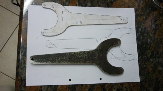
We got the Spanner (pic below) cut out from 10mm Mild Steel.
The Suppliers said the Pin Diameter Hole in the Flange is 6.20mm and we would require 6.0mm Pins on the Spanner for a span of 75 mm which we have spotted on the metal.
Only thing is we would like to use 6.00 mm press-fitted Hardened Dowels instead of Drilling and Tapping for Set (Grub) Screws.
We hope these Pins would remain secure enough.

The question now is what hole Diameter do we Drill ???
Would a 5.50mm Hole that will be Gas-torch-pre-heated suffice or do we go for 5.90mm or lesser ???
We could freeze the Dowels overnight and use them in the pre-heated Hole to get a nice strong press fit
Do regret bothering U with these petty obvious Q's. But we would like to get this right first time without Mr Bozo making an un-called for appearance !!!

The good news is that the Flange and the Bushing is still available from the machine Suppliers and we will be Ordering these in the interim
So we really need this Spanner and it has to be the correct fit as we would loathe to do what others did to deface it like this.

Look forward to hearing from U
TIA
Kind regards
aRM011.JPG
 
A normal press fit would be to make hole 0.025 mm smaller than the pin in this size range. You could go maybe 0.050mm undersize on the hole. Smaller than that I think the the pin won't fit well.

Nice job on the spanner. :encourage:
 
  • Like
Reactions: ARM
Back
Top