Bridgeport Power Feed 6f Motor Mount Question

Checked the manual for the 6F, you are correct that the speed pot is specified as a log taper as opposed to linear, although I did read in another thread that there where some variations in the power feeds as to some using linear vs. log taper. The idea with a log is that you have better low speed control with a log, as opposed to linear. You should be able to determine the type used by the range on the speed scale (log would have closer spacing at the higher end). A 500 ohm log/audio taper pot in a sealed version is very uncommon. Another thing to consider is that often manufactures specify custom tapers for their pots, so I do a lot of audio tube tester repairs and many of the pots have unusual tapers/steps making them unobtainable.
They do sell replacements for$23. In either case, whether linear or log, it should make no difference as to the drive working, just the speed at a given dial position.
http://www.icai-online.com/6f-b-c-front-panel-housing/
http://www.ebay.com/itm/500-OHM-LOG...TENTIOMETER-LONG-SHAFT-53C1-NOS-/232472291144
 

Attachments

  • Bridgeport serial number 4301 and older SeiresIPartList.pdf
    1.5 MB · Views: 4
Checked the manual for the 6F, you are correct that the speed pot is specified as a log taper as opposed to linear, although I did read in another thread that there where some variations in the power feeds as to some using linear vs. log taper. The idea with a log is that you have better low speed control with a log, as opposed to linear. You should be able to determine the type used by the range on the speed scale (log would have closer spacing at the higher end). A 500 ohm log/audio taper pot in a sealed version is very uncommon. Another thing to consider is that often manufactures specify custom tapers for their pots, so I do a lot of audio tube tester repairs and many of the pots have unusual tapers/steps making them unobtainable.
They do sell replacements for$23. In either case, whether linear or log, it should make no difference as to the drive working, just the speed at a given dial position.
http://www.icai-online.com/6f-b-c-front-panel-housing/
http://www.ebay.com/itm/500-OHM-LOG...TENTIOMETER-LONG-SHAFT-53C1-NOS-/232472291144

I bought the icai replacement. Will be here tomorrow. So if that isn't going to fix anything I'm still in the dark.

Seriously going to crate the entire motor/gearbox/controller as one unit and send it back in.

Paul
 
Well that was a strike. I think I need another diagram. I'm still getting that bump from the motor just when go to return it to neutral position...just before it gets to it's neutral position...and not every time. As well, just from Left to center position... Perhaps that generic drawing I was using has the wrong wiring layout? Not sure how to verify it. Is there a different diagram in that book with the part numbers...

(edit) I found that manual copy and am trying to search it...

Paul
 
In motor speed applications the pots are commonly linear, it is just acting as a voltage divider. The pot is specified as a 2W 500 ohm, Honeywell make decent pots. It could be that the leads to the pot are wired incorrectly. You should be able to check voltages to the motor (90VDC) and the field coil (100VDC), you could do this with the motor disconnected. If you are not getting voltage, then you need work backwards, check the voltage at the control board terminals and then to/after direction switches.

http://www.atechfabrication.com/information/Bridgeport_Feed_Controller.htm

Ok I tested these with the motor disconnected. I assume to check I was supposed to go from each feed wire to ground. If this is right then my voltages are wrong.
I got in the "neutral" switch position 57 volts for the field wires. 69-67 volts on each of the motor armature wires. In the engaged position...going either right or left I got 80 volts on the field wires and still 67 to 72 volts on the motor armature wires.

Paul
 
Motor voltage would be measured between the poles of the motor, 1 (203) and 2 (204) for the armature, and 8 (210) and 3 (205) for the field coil. Make sure the speed pot is maximum, I believe the the voltage to the motor armature should decrease when decreasing the pot.
 
Motor voltage would be measured between the poles of the motor, 1 (203) and 2 (204) for the armature, and 8 (210) and 3 (205) for the field coil. Make sure the speed pot is maximum, I believe the the voltage to the motor armature should decrease when decreasing the pot.

OK on 203 to 204 in neutral I get a wild moving -90 to -170 mV. On 210 and 205 I get Zero at neutral and 170 volts engaged.

Edit: Also for wiring I'm referring to the BP_Mill_Series1_manual.pdf pages 124 and 125

Paul
 
So it sounds like you are getting voltage, the fluctuation in voltage on 203-204 is because it is rectified but not filtered DC. I would expect the armature voltage to decrease when the speed knob is decreased. So if you are getting voltage to the motor, the drive should be working. I have not worked on these type of drives so I am making some assumptions on how I believe they operate. Maybe if you can give some specifics as to what the drive is actually doing and what is not working.
 
So it sounds like you are getting voltage, the fluctuation in voltage on 203-204 is because it is rectified but not filtered DC. I would expect the armature voltage to decrease when the speed knob is decreased. So if you are getting voltage to the motor, the drive should be working. I have not worked on these type of drives so I am making some assumptions on how I believe they operate. Maybe if you can give some specifics as to what the drive is actually doing and what is not working.

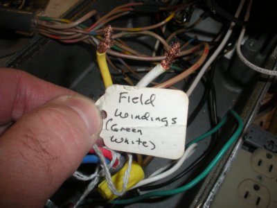
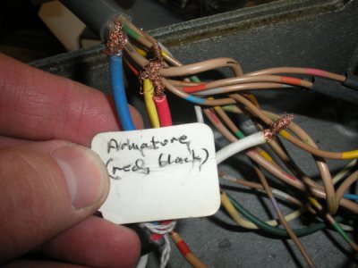
All I can get out of it is a little bit of motor movement when switching back from "Left" position to neutral position. That's about all I can explain? The motor was repaired and had the commutator replaced by icai and they tested the board. Maybe it's the wire harness from the motor. Could be crossed inside I can't tell because the colors are different in the cord. But they are grouped and each set of two has at least one matching color. One would think that they connected the white wire to the white wire etc. The the default remaining wire of the group should go to the other connection... :(

These are the wires from the motor.

DSCN6328.JPG

DSCN6329.JPG
 
I am a bit of a loss as to further suggestions without having hands on evaluation. It could also be a polarity issue of the wiring. If I suspect a wiring issue, I will sometimes make up a new wiring harness, but having not seen one of these I am a bit in the dark. My suggestion at this point would be to call Icai and they should be able to give you better directions as to testing/evaluations.
 
The motor should have 5 wires coming out of it. One for ground, two for field and two for armature. Take out a brush. With your ohm meter find the two wires with resistance. Sorry, can’t remember what it should be? ~400? Mark the wires "field". Put the brush back in. Then two more wires will have resistance "arm". ~7? The last wire should be ground to the motor case. ~0. The other wires should have infinity to case ground. Again sorry, I cannot recall the typical found resistance. But hopefully you get the idea of what kinda resistance range you want to look for…Good Luck, Dave.
 
Last edited:
Back
Top