Building a small Machinist Vise

Even cheapie squares can be trued up. That's what they make files for. :)

Just in case you don't already know, the way to check a square is to mark a line off of it and then flip the square to the other direction and mark a line next to the first. Adjust until it marks the same from either direction.
 
Have you made sure the datum your using to true up the fixed jaw is true? It's imperative to start with a proper square. Any variation on the contact surface will transfer to the work and no matter how many cuts you take on the back jaw you will keep getting the variation. I learned that in a book but I made sure I ignored it at least once. Just to make sure it really would waste my time and materials ahahaha. Just flipped the block in the wrong direction when squaring my stock and made a real crooked v block.
 
I think I made some decent headway this evening. I was following Jim's suggestions and to start I ran an indicator across the fixed jaw on my mill vise, and I found it was out of alignment with the table. It was out by quite a bit, it must have moved since the last time I checked it. Anyway, I realigned the mill vise, then clamped the mini vise in the larger one (with the "back" of the fixed jaw against the fixed jaw of the mill vise) and indicated the face of the rear jaw. It was off a little so I took a skim off that face again. It then indicated true. Then I used the indicator to get a feel for how much "slop" was in the movable jaw (trying to understand how much rotation of the jaw the rails allow) -- to my great surprise I was unable to measure anything more than about a quarter of a thousandth of play at the edges of the jaw face. My process for measuring this was simply to move the jaw (freehand) against the indicator, then try to twist the jaw without letting it slide forward or backwards - so it's certainly open to human error, but try as I might I couldn't introduce any noticeable twist.

I decided that since there didn't seem to be any appreciably twist introduced by the locking screw that I should be able to just lock the movable jaw and run an end mill across the face of the movable jaw. I did that, and after milling it ran an indicator across the surface again and it indicated true. When the two jaws are brought together they seem to be very true left-to-right, but I still have about a .0025 gap (according to my highly precision Harbor Freight feeler gauges) at the very top of the jaws. The gap seems very consistent across the top edge, ending about a third of the way down the face (or more precisely, getting below .0015 (the slimmest of the feeler gauges I have) at that depth).

I consider this a pretty good improvement. When I clamp a piece of 3/8 aluminum plate in the jaws (and tighten to what I consider a reasonable level) I am unable to twist the plate out of the grip of the vise.

David - I watched that video, interesting how much time the author put into 'perfecting' a wood plane - personally I'm not sure how measuring the chip with a micrometer tells him much more about the plane than the sharpness of the blade, but whatever... The techniques he used to verify squareness are pretty-much what I've done (hold a square up to side and look for light. TO the best of my ability to discern, the sides all seem square to the bottom and the top seems square to the sides. I don't have a precision straight-edge, but I'll check for flatness with edges of the squares tomorrow. I suppose I could try to the true up the jaw faces to each other using a file, but frankly I suspect I'd do more harm than good at this point, but I may give it a shot in any case - I think I have plenty of meat left on the faces of the jaws.

Thanks again guys for suggestions!
 
David - I watched that video, interesting how much time the author put into 'perfecting' a wood plane - personally I'm not sure how measuring the chip with a micrometer tells him much more about the plane than the sharpness of the blade, but whatever...

Thanks again guys for suggestions!

I cringed every time he was saying it was "unusable." I guess he doesn't know what that little lateral adjustment lever is for. I also figure he is unaware of the Japanese way of creating the hollows that he is working so hard to remove.

The micrometer shavings fetish? Well, there is a lot of that in the woodworking world. They even have competitions for it. Of course it has absolutely nothing to do with actually making anything.

But anyway, he does a lovely demo of scraping and squaring. :)
 
I'd shim up the back of the minivise and take a .0025" wedge off the movable jaw.
 
Using some of the ideas from the video David posted above I took another look at the vise. As far as I can tell the bottom is reasonably flat, and the sides are as square to the bottom as I could hope (checked with my machinist squares (which also seem reasonable square)). The top side of the vise (which the movable jaw rides on) is square to the sides, reasonably flat, and indicates parallel to the bottom. However, the back of the vise (rear side of the fixed jaw) is not 100% square to the bottom. I would say it's out by about .003 over 2". The faces of the jaws are also visibly out of square with the top of the vise (using the square and looking for light). I could see with the back out of alignment that the jaw faces could have been milled parallel to the back (as it was the side against the fixed jaw on my mill vise when I faced the jaws last), what is odd though is that both the fixed and movable jaws are "out" about the same amount, but in both cases the top edge shows the gap (with the square on the "top" side of the vise... Not certain how the movable jaw got cut basically the reverse of the fixed jaw unless the mill was slightly tapered as well?

Anyway, I was going to fix the rear face of the vise. But after indicating my mill vise to ensure it's fixed jaw was still true (in both X and Z axis), when I placed the little vise in the mill vise (back side up, bottom against the rear jaw, sitting on short parallels, with a piece of copper wire between the movable jaw and the "top" of the small vise, the top surface (back of the small vise) indicated it was flat? I ran the flycutter across it anyway, taking almost no cut, and the cutter touched everywhere the same amount (almost nothing, just enough to mark the surface). The only thing I can think is that the combination of only clamping only the last inch of the small vise bottom, and it sticking out of the mill vise 3", and potential jaw lift in my mill vise (it's a Chinese vise, not a Kurt) is introducing enough tilt that I'm left with the vise being held slightly out of straight...

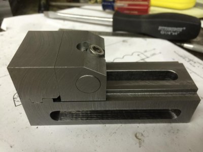
After that I decided to go ahead and give hand working the jaw faces a shot. I used the squares against the top side of the vise, and started hand filing the faces of the jaws. After maybe a half hour of slowly working them I was left with this:
6B50122D-FC22-4DE5-BC43-DBF7CD2BCC2A_zps2aydr88e.jpg

The faces read square to the top side of the vise (which indicates parallel to the bottom of the vise), there is no visible crack between the faces (I can see no light between them) and I can't fit my smallest feeler gauge (.0015) between the faces anywhere. I was careful not to make the faces concave so they aren't just touching around the edges. Anyway, I'm pretty pleased with the results - not what I would have expected, that hand-working with a file would be more "precise" than using the mill, but that's what I discovered...

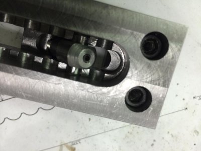
I also had to make one final tweak to the design to make the "retainer slot" closest to the fixed jaw end of the vise usable. I had to mill out a little extra space to make room for the pivoting grabber-thing...
F25E4F9F-6C1D-460F-9A68-12771EECCFA2_zpsw4gyv5rc.jpg

I'll probably take a shot at squaring up the back of the vise with the files. And I'm planning on making a dedicated wrench for tightening it. But other than those, I think this project is basically done.

Thanks for the input along the way!

6B50122D-FC22-4DE5-BC43-DBF7CD2BCC2A_zps2aydr88e.jpg F25E4F9F-6C1D-460F-9A68-12771EECCFA2_zpsw4gyv5rc.jpg
 
Looks really nice.

The machines are nice but nothing you can't do otherwise. It just takes careful work and patience. Right now, you are really at the starting point if you wanted to get crazy accurate with it. Just touch it to the blued surface plate and scrape carefully until it is perfect. There are tricks to make it go faster and to keep from going too far, but basically it is just that simple repetitive cycle.
 
Nice job. I'm still not sure why the surfaces didn't machine true, but I think you're right, it may have lifted in the mill vice. A lot of times when I need to get really accurate in the mill, I use a known good angle plate or just clamp down to the table to take out some of the variables.

It may be time to work on your mill vice a bit. I had an import 6 inch mill vice, Kurt style, and had to do some rework on it to get it accurate. The fixed jaw would flex about 0.0025 at the top when I tightened it. I replaced the original 1/2 inch cap screws with 5/8 inch cap screws and tightened them all I could pull on a 30 inch breaker bar. Pretty much eliminated the flex problem. I'm going to do the same thing with my Kurt vices I have now.
 
Gread job, I think you pretty much nailed it. Now try to mill a perfect little cube to see how you did.
 
You've done a wonderful job making a great tool!
this could be a case of "a job well done is its own reward," but I think you'll be rewarded with good results every time you use this vise!

Doug W
 
Back
Top