CAD Questions

Back in my carpenter days I didn't hardly ever need any drawings to throw something together, however now beginning my journey into machine on my mini lathe I think it would be very helpful to be able to draw something up before beginning a project.

I did a search here and found lots of good info but not being a techie I'm not sure which CAD programs I should be pursuing. It appears that Fusion 360 and similar programs are for designing parts and 3D printing them which I have no interest in, at least right now. I just want to draw parts with dimensions that I can make. Is Fusion 360 overkill for my needs? Are there any other programs you would recommend?
Thanks!
I started all this about a year ago, intent on scratchbuilding HOn3 steam locomotive models. My first attempts at the frame were done with LibreCAD, a free open-source program you can download and use without restriction. My first attempt with it was a locomotive frame outline that I sent to OSHCut as a .dxf file from LibreCAD for laser-cutting from nickel silver. The program is just 2D, which might be a good way to ease into CAD, and it has some support for producing drawing renders. BTW, the LibreCAD->OSHCut thing worked great, nicely cut profiles that would have taken me hours to do poorly by hand... :big grin:
 
I've used LibreCAD and it's ok. Used for quite a few years before taking the jump to 3d. Sort of like pen and paper, in a way.

3d is a different animal, but much more powerful, as you can create assemblies and check for range of motion and interference a lot more easily. Nowadays, I just build a solid model, check things for correctness and make critical section views, if required. Want standard drawings in the three planes, no problem. A couple of clicks and you have them. Add dimensions to the drawing and off to the shop I go. Sorry to use this expression, but it's a game changer. Want a non standard view, no problem.

If you use parametrics, you can create different size versions of a basic design, which is pretty neat. I have used the integrated spreadsheets to enter in dimensions, if I want a change, I can simply change a value in the spreadsheet and watch the model change.
 
Of late, I've been using OpenSCAD as my 3D modeler. Everything is script-based, you write "cube([5,10,1]);" in the edit window, and you get a block of those X, Y, and Z dimensions in the render window. You make cylinders the same way. With that, and operators to union() things together and difference() to subtract one from another, and a couple of extrusion operators, do enough of them and you get a steam locomotive:
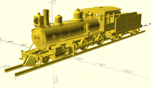

2023-10-19_stl_integration-800x600.png

Now, I do not recommend this program generally. Get a good interactive program like Fusion 360 if you're just starting out...

However, I think an approach like OpenSCAD has its benefits. The big one is that all the design decisions I made to model that locomotive are in a script somewhere. It's like reading the mouse move/clicks that do the same thing in an interactive program. I try to insert comments with the code to label them and sometimes describe what's going on, so there's that. Organizing the model was simply a directory hierarchy. I can use tools from my programming background to manage the model; if you're familiar with unix 'make', I use it to run OpenSCAD from the command line to re-render .stl files for the models that changed. Yeah, I'm losing people here, but it just fit my way of thinking developed in a long time writing computer programs.

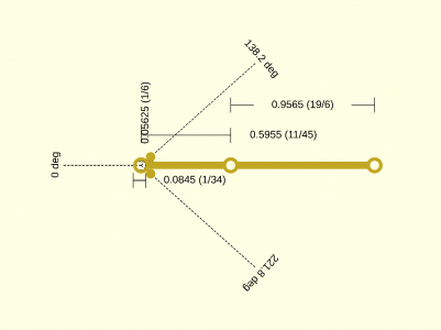
Of late, I've been using OpenSCAD and my already-modeled locomotive parts in doing drawings for machining selected parts that need to be "functional", that is, support the moving parts of the mechanism, rather than the "decorative" parts like compressors, generators, the boiler and cab, etc. My current example is cutting the siderods, which run between the drivers to transmit the force from the piston. The part is to be cut from 0.02" brass, and I'm working on a milling procedure to step through the radii and traverses (doing this manually, no CNC). Making rounded segments that meet the rod is challenging, accommodating the 1/16" endmil diameter, but instead of doing all the trigonometry required to calculate the arcs I'm just modeling the end mill in OpenSCAD, rotating it around the radius and seeing where it ends up:
siderod_scalelinkparts.png

The two circles on the left on each side of the rod are the end mill positions after first being centered on the bearing, translated left to put the edge on the bearing OD, the rotating it around until it "touches" the rod. Given that my rotating table will be set to zero on the rod centerline, I can turn left to 138.2degrees and then right back to 221.8degrees to cut that arc.

I also made a "turns/ticks" function in OpenSCAD to take a dimension and calculate the handwheel turns and subsequent ticks for my Sherline to move that dimension. Those are the (turns/ticks) annotations to the right of the dimensions.

Now, I'm pretty sure you can do the same thing in any other CAD program worth it's salt, just a few things I came up with to make my machining go easier...
 
I've been using AutoSketch for about 18 yrs. It is a no longer supported AutoDesk 2D CAD product and is essentially a simplified, home user version of AutoCAD. Even though it is no longer supported, it is still available as a download, version 10 with a lifetime license key for around $150 (do a web search for "AutoSketch 10).

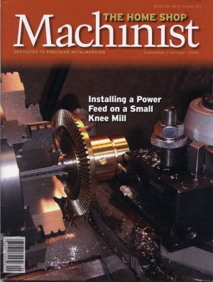
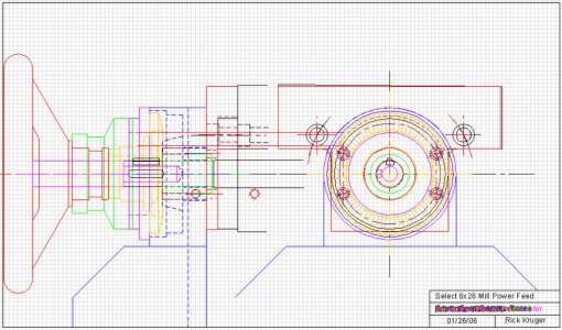
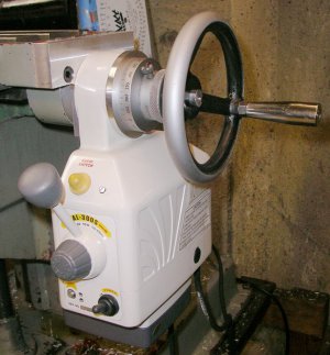
It is a fairly well featured system that allows complex drafting. One of my first projects were the drawings for a powerfeed adaptation to my Select 6x16 mill table, that became a cover page article in Home Shop Machinist in 2006 (Sept/Oct). Drawings in the article were done with AutoSketch. The image of the total assembly drawing below is way over complicated, but is an example of how complex and detailed drawings can be made.

My drafting process is to draw everything in assembly, each part on a different layer and that part's associated dimensions on another layer. If I machine the parts to the dimensions in the drawings, almost always, they fit and work. I do frequently discover errors or adjustments that need to be made, but it has been an effective process for me.

I have been trying to add 3D modeling, using Fusion 360, to my repertoire as there are many projects/parts that can be better produced using 3D printing, but it has been a slow process. What I have found is that, while 3D modeling is very useful and fun, 2D modeling will always be the largest basis for my machining projects, if just for the joy of the machining.

Rick
 

Attachments

  • Cover.jpg
    Cover.jpg
    304.4 KB · Views: 5
  • Power Feed Drawing.JPG
    Power Feed Drawing.JPG
    207.4 KB · Views: 5
  • MountedPowerFeed.jpg
    MountedPowerFeed.jpg
    114 KB · Views: 5
Back in my carpenter days I didn't hardly ever need any drawings to throw something together, however now beginning my journey into machine on my mini lathe I think it would be very helpful to be able to draw something up before beginning a project.

I did a search here and found lots of good info but not being a techie I'm not sure which CAD programs I should be pursuing. It appears that Fusion 360 and similar programs are for designing parts and 3D printing them which I have no interest in, at least right now. I just want to draw parts with dimensions that I can make. Is Fusion 360 overkill for my needs? Are there any other programs you would recommend?
Thanks!
Absolutely.

Graph paper and pencils built nations and there's no learning curve.
 
Absolutely.

Graph paper and pencils built nations and there's no learning curve.
Obviously yes. Certainly for relatively simple things, and even for complicated stuff. But the complicated stuff gets hard to check, that it was done right. CAD can help you find those problems. CAD can also help you make more blunders, faster!

CAD is a tool like many others. It can be extremely helpful. Add ons can augment it's capabilities to create complete Bills of Materials, which are tedious to compute. CAD has mostly taken over in industry, because it makes the design and fab process more productive. And this productivity is good enough to put up with it's costs and training.

Sometimes all you really need is a pencil sketch to let you know if something is going to work. Nothing wrong with that!
 
I often start my designs on with a pencil sketch to help get the general idea of what I am going to build. Helps me to anticipate the bigger problems so they get avoided early. Then I quickly move to CAD for all the reasons that @WobblyHand said.
 
Thanks everyone for your replies!

I didn't realize how expensive some of these programs are. I do not want to invest in a program and find out it's not for me.

Just looked briefly at FreeCAD and it looked interesting with some good tutorials on Y/T as well. I'll check out LebreCAD too.

The nice part about Fusion 360 is there’s a free version for hobbyists. It doesn’t have all the features of the paid version, but from what you describe, it sounds like you wouldn’t need them anyways. I am still using the free version and it is great for creating drawings in my shop, but the real power of the program is building the entire project in one model, makes it really easy to what needs to be changed before machining starts.

Old school drafting is always a possibility, it doesn’t have the advantages of a modeling software as Wobblyhand mentioned above. Inheritance Machining did a video on his YouTube channel on drafting by hand that you might be interested in watching to see which way to go. He uses a CAD program at his day job and decided to do drawings by hand for his home shop.
 
CAD Models are a powerful tool, if you are setting up an assembly and need to machine the individual parts its very useful and if you are trying to fabricate a part to replace an existing part. The philosophy is build it in the machine first and make certain it will work then use the 3D part model to build the drawing.
 
There is a certain Zen to manual drafting that I miss. Not enough to give up CAD but ...
 
Back
Top