Compound rest degree

Mine is generally set at wherever.
If you are doing a very precision part - either facing or turning - you can set it at 45. That way you can increase the depth of cut by halves.
 
Hello all, I just had a quick question that I’m sure will have a multitude of different opinions but I’m trying to figure roughly a good place to position my compound for most operations. Got a few plates that need facing for one but a good place for common operations I guess is what I’m asking. Right now my compound is at 29 degrees. Thanks In advance
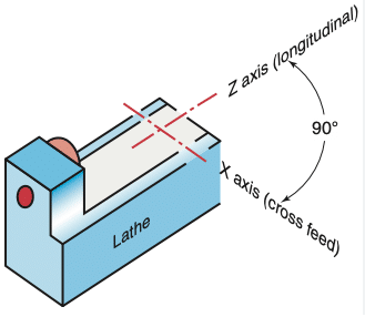
One thing to consider is the orientation of your compound. On typical old American iron, the compound at 0 degrees will give travel on the X-axis or parallel to the cross feed. In this case, set your compound to 29.5 or 30 degrees to cut a 60 degree thread.

On import lathes, the compound orientation is typically turned 90 from USA iron. A compound angle of 0 degrees will give travel on the Z-axis or parallel to the longitudinal feed. In that case, set your compound to 60 - 60.5 degrees.

There are lots of threads here where a member has a bad looking thread because of this orientation difference.

1713101324272.png
 
Thank you
One thing to consider is the orientation of your compound. On typical old American iron, the compound at 0 degrees will give travel on the X-axis or parallel to the cross feed. In this case, set your compound to 29.5 or 30 degrees to cut a 60 degree thread.

On import lathes, the compound orientation is typically turned 90 from USA iron. A compound angle of 0 degrees will give travel on the Z-axis or parallel to the longitudinal feed. In that case, set your compound to 60 - 60.5 degrees.

There are lots of threads here where a member has a bad looking thread because of this orientation difference.

View attachment 486579
i understand what your saying. Mine is an old Enco built in 86 I believe. It came from a gunsmith’s store and he had scrubbed a mark on the compound I believe at 60 degrees. I wondered what that mark was there for,lol
 
Also attempted to cut a 1/2 -28 thread with the compound set at 29.5. I managed to cut a thread but not sure if it was what I was aiming for. Seemed like the threads turned out really thin and sharp. Like razor sharp. Also looked as if the metal was torn away vs cut cleanly. May have been the cast steel bar stock I was using but not sure. I was using a threading insert tool as well
 
How did you calculate the thread depth?
I was taught that most US threads are ANS which have flats on the crest and root and you have to grind the tip of your tool with the correct width flat.
Then you use the formula .750/N where N is the # of threads per inch to compute the depth you turn in your compound. The only time you have your your tool ground to a sharp point is when cutting V Sharp threads which is seldom used except on very fine threads like those on a micrometer.
As to your lumpy gravy finish that was likely the steel you used - like maybe some hot rolled which is low carbon and leaves a very poor finish.
A higher carbon steel like cold rolled usually will give you a much better finish.
Or for some nice threads buy a piece of 1144 or "stress proof" which is an easy machining steel that will make some real nice looking threads
 
I don't use the compound slide a lot but to avoid turning tapers, it has to be set to an accurate 0° angle. Accurately setting up the compound slide is time consuming so I always keep it at 0°.
 
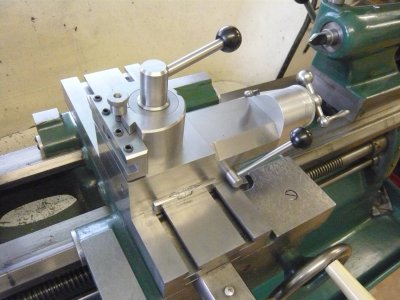
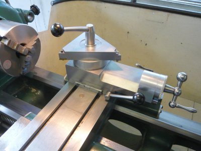
I modified my lathe cross slide by adding premachined steel tee slots bolted on from the underside. Then I made a new topslide of my own design that can be moved anywhere and set at any angle on the cross slide. It is locked solidly in position by the lever on the side of the topslide. So setting it to an angle or location is simple and quick.
Alan
Photo 8 New Topslide.JPGPhoto 11 Inverted triangular toolholder.JPG
 
I modified my lathe cross slide by adding premachined steel tee slots bolted on from the underside. Then I made a new topslide of my own design that can be moved anywhere and set at any angle on the cross slide. It is locked solidly in position by the lever on the side of the topslide. So setting it to an angle or location is simple and quick.
Alan
View attachment 487482View attachment 487483
Nice work.

You mentioned last year in another thread that you'd detailed it in MEW. Do you remember what number were those articles in? (I've only been getting them this year, nice to have an actual physical magazine to flip through every month) I'll have to see if I can get the back issues. :)
 
Nice work.

You mentioned last year in another thread that you'd detailed it in MEW. Do you remember what number were those articles in? (I've only been getting them this year, nice to have an actual physical magazine to flip through every month) I'll have to see if I can get the back issues. :)
Hi SouthernChap,
I did a comprehensive write up with detail drawings and operation description in Model Engineers Workshop Nos 119, 120 & 121. That is October, November & December 2008. It was mainly based on a Colchester Chipmaster or Bantam, but I also described how a Myford ML lathe could be adapted. In fact any lathe can be sutably modified.
Alan
Thank you. I'll see if those back issues are still available.

Currently have a little Chinese 7x, so will probably wait for an upgrade to a lathe worthy of this (which itself awaits an improvement to my finances!), before attempting it; there's a long enough to-do list of fettling and rigidity upgrades already for the 7x.
 
Back
Top