Considering making my own pin gage set

A pin gage is not a turning job made on a lathe, it is a cylindrical ground precision tool. They will need to be accurate within at least a tenth and also parallel within .0001" or so. They are hardened to resist wear, and made from steel with more chromium, etc, so they will be less likely to rust. They also need to be straight. Maybe it would be worth making the first 5 smallest ones from .010 to .015" first and see how that smaller project goes for you... Do not cut yourself any slack, each one needs to make the specs...
 
I now believe that this is not practical, if for no other reason than the import set is less expensive than the raw stock.

I can practice turning to a diameter and facing to a length on the scrap that I already have.

A similar argument goes for making a gage block set.

Thanks to everybody who weighed in.
 
If you still want to try it out, you can make gauge pins as you need them, based on projects. You can try a go/no go gauge or a fixture pin on an as-needed basis and still get the experience you're after. A toolpost grinder would probably work well enough for a home shop, but it's a long, long way to commercial grade accuracy from there.
 
I once made a set of go/no go gages to check ammo, in my case, pellets for my pellet rifle. These were to be used to check the size of holes that would tell me if the head of the pellet was a specific diameter, as there is (or was) some variability in head size and certain sizes shot best in my airguns. Pretty important for competition purposes.

I needed sizes of 0.173", 0.174", 0.175" etc up to 0.179", for six total (airgun barrels are generally choked a bit). Actually, I worked in tenths, with each one to be within - 2 tenths of the desired size but not oversize. It was pretty easy to get a few done, as no matter what, I would end up with something that met my requirements in one of my sizes. But, hitting those last few was incredibly difficult, especially the last one. Turns out hitting 0.1768-0.177" is not that easy. I ended up with multiples of the smaller sizes, since i could always take just a little more off. And I may have fudged a bit on the biggest one, looser tolerance since it was bigger, I guess.

It was a semi fun and semi frustrating project. You might have an easier time with a new lathe than I had with my beater Logan. And yes, it would be good practice for you. But don't expect to be able to make a full set of gage pins.
 
Just to give a feel of something similar, I just finished making a dozen valves for my 5-cyl model radial engine from 303 stainless. And I'm real glad that's over with. They stems are nominal 3mm (0.1181) and I held myself within +/- 0.0001" because they must fit a matching reamed hole in the valve cage. The skinny aspect ratio requires that it be supported with live center. You wont be able to turn skinny pins down cantilevered from the chuck without some kind of end support. That's another difference between a regular lathe and centerless (or somehow supported) grinder where gage pins are made.

Grinding wasn't an option for me so they were turned down ~0.002" oversize, then a series of simple split laps were used with finer grade pastes. Its messy time consuming work. I used a 3mm gage pin (price about 2$) to calibrate my lapping block as it needs to be redressed with wear. Stainless typically doesn't like to be crept up on thou by thou (it can work harden). It also can get pretty warm with heavier cuts so in this range you either have to account for expansion or wait till it cools to reference temperature when measuring.

Anyways, its good to have some experience like this, it facilitates making some useful things. Make a few do-dads just to learn & have some fun, but I'm guessing the novelty of making a set will wear off in a hurry. And even if they are bang on diameter, you are left with something relatively soft compared to real pins which are hardened before being ground.
 

Attachments

  • IMG_2259_edited-1.jpg
    IMG_2259_edited-1.jpg
    47 KB · Views: 20
  • IMG_2270_edited-1.jpg
    IMG_2270_edited-1.jpg
    31.5 KB · Views: 18
  • IMG_2272_edited-1.jpg
    IMG_2272_edited-1.jpg
    51 KB · Views: 17
  • IMG_2306_edited-1.jpg
    IMG_2306_edited-1.jpg
    103.4 KB · Views: 18
  • IMG_2307_edited-1.jpg
    IMG_2307_edited-1.jpg
    89.5 KB · Views: 18
  • IMG_2338_edited-1.jpg
    IMG_2338_edited-1.jpg
    102.7 KB · Views: 19
You could modify a height gage scribe to accept a small pin, held parallel to the surface plate. Then as long as you can hold your bore parallel, you can measure the bore and add the diameter of your pin. Modify pin as necessary for feature. You could even modify it to accept m2/m3 threads and screw in cmm probes or whatever.
 
It would be nice practice getting a good surface finish on your new lathe.

Early on it would be very easy to get them going because if you need all sizes you can just stop with any size once it looks good and it will be one of the sizes. Will be more challenging with needing to make exactly the right size for the missing sizes needed but after a couple hundred you will have better skills.
 
There are lots of useful tooling projects you can make for practice. Spindle stop for the lathe, vise jaw stop and table stop for the mill. The list is nearly endless. Any of these would be more useful, educational and entertaining than making gage pins.
1577495848568.png
1577495791836.png
1577495937726.png
1577496122452.png
 
I will buy a pin gage set one day.

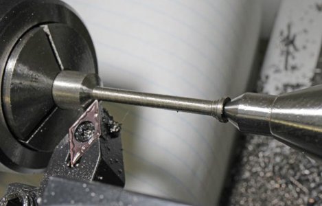
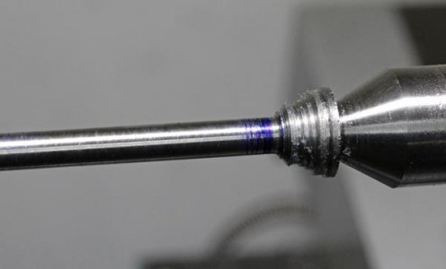
For fun, I ended up making four pins equal in both length and diameter: 1/4", 1/2", 3/4' and 1". My surface finish was an issue, but I got them to within about .0003". The surface finish was the limiting factor, and I am reluctant to use emery paper because the ways are brand spankin' new. It was good practice for turning to a diameter and facing to a length on my new lathe.

If I were to do it again, I would take down the last .0008"-.0010" with a smooth file or emery paper. I lapped one of two few faced ends, but I was in danger of going under the specified length.

Along the way, I realized that my DRO (on a PM-1030V) has a resolution of about .00020"; that is, the finest adjustment that I can dial to is .00020". So I am not able to dial in .0001" using the handwheel. I would have to use an indicator, and I don't have a test dial indicator with tenths graduations.

The 1/4" X 1/4" pin was really small in the 5" 3 jaw chuck. I don't think that I could chuck up a 1/8" X 1/8".

At one pojnt, I bumped the cross slide handwheel, dialed in for a finish cut and proceeded to scrap that pin. That scrap became the 1/2" pin. After that, I steered clear of the handwheels when measuring the part in the chuck (and kept track of my location on the DRO).

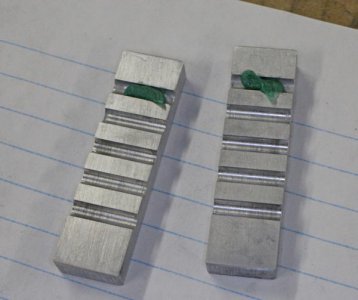
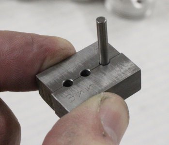
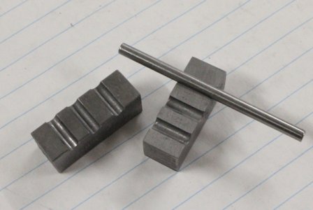
Here they are. These are the first things that I made with my first lathe.

IMG_7499.JPG
 
Last edited:
Nice work.
I've never sprung for a set of gauge pins but there have been times I could use them. For standard fractional sizes dowel pins make a viable substitute.

Greg
 
Back
Top