- Joined
- Jun 17, 2011
- Messages
- 2,062
Nice work on the grinder.
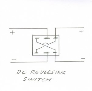
If anyone is using one of these motors for a project and wants to make it reversible, it should be quite easy. You'll have to take the motor apart to get to the wires attached to the bridge rectifier. There should be one marked with a "+", one with a "-" and two with "~" markings. Tag the wire from the "+" and "-" with tape to show where they came from. If you want the 'normal' rotation to be opposite what it is now, reverse the markings.
Solder new wires onto the two bridge terminals and mark them as they are on the rectifier. bring all four wires out of the motor and into your junction box. You may need to lengthen the original wires that you took off the rectifier terminals. You will have 6 wires coming out of the motor. Two will be the original AC supply leads from the switch or dimmer. Leave them connected. You will need to add a DPDT (double pole, double throw) switch to your junction box, wired as shown. Make sure the switch is rated for at least 120 vac (or 170 vdc) and more than the current shown on the motor label. Note that it doesn't matter whether the wires on the left of the drawing are coming from the rectifier or the motor brushes. Just keep left with left and right with right. You'll have to add the crossover wires to the back of the switch. Just make sure they're insulated and don't short each other out.

Last edited by a moderator:

